This helps you quickly interpret patents by identifying the three key elements:
Problems solved by technology
Method used
Benefits of technology
Benefits of technology
The invention is an atomizer and electronic cigarette that can increase the amount of smoke produced. The atomizer includes a cartridge with a liquid storage area and an electric heating element for atomizing the liquid to produce smoke. A first liquid guide cloth is used to ensure even distribution of the liquid to the heating element. The electric heating element is a spiral structure that increases the contact area and prevents premature burning of the liquid storage cotton. This design increases the yield of products and ensures the safety and service life of the atomizer.
Problems solved by technology
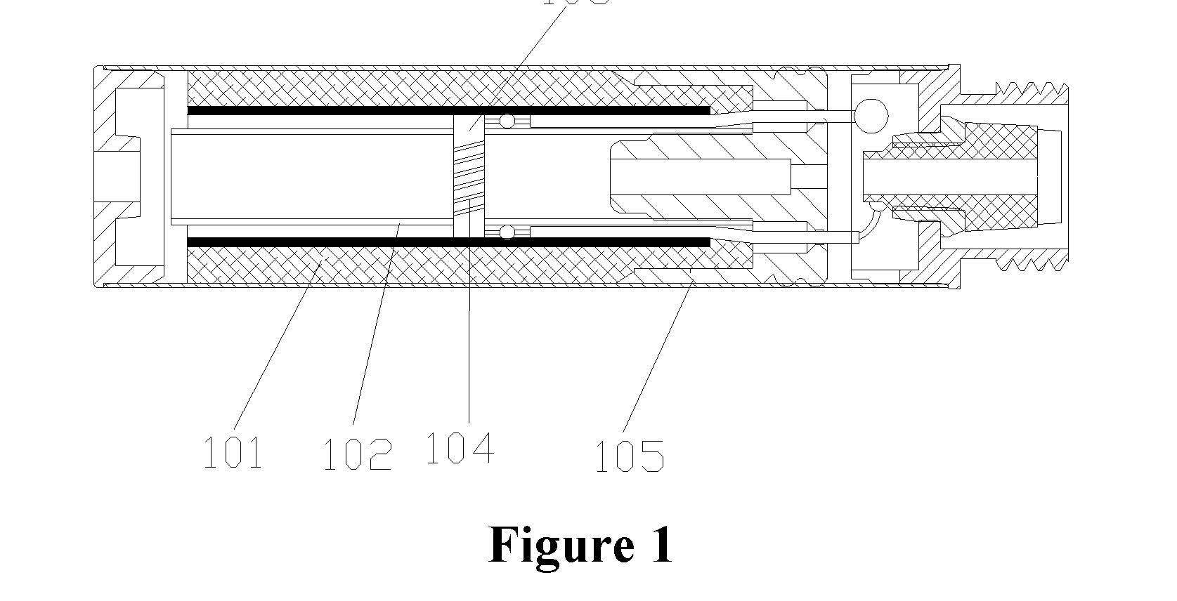
However, such approach is apt to cause the liquid storage cotton 101 to be burnt, which negatively affects the service life of the electronic cigarette.
However, since the electric heating wire 104 is of soft nature and the electric heating wire 104 arranged by winding has spaces formed between spiral coils, if the electric heating wire is placed vertically, the spiral coils may be extremely likely to contact with each other due to gravity or vibration, such that power of the electric heating wire fluctuates largely, and further causing the smoke volume to fluctuate largely, i.e., as the number of the spiral coils in contact with each other varies, the generated smoke volume varies, resulting in an unstable smoke volume.
When the power is too big, the glass fiber wire 103 may be burnt; therefore, the desirable effect may not be achieved, the service life of the atomizer may be negatively affected, and reject ratio of products during manufacture is high.
Method used
Image
Click on the blue label to locate the original text in one second.
Reading with bidirectional positioning of images and text.
Examples
first embodiment
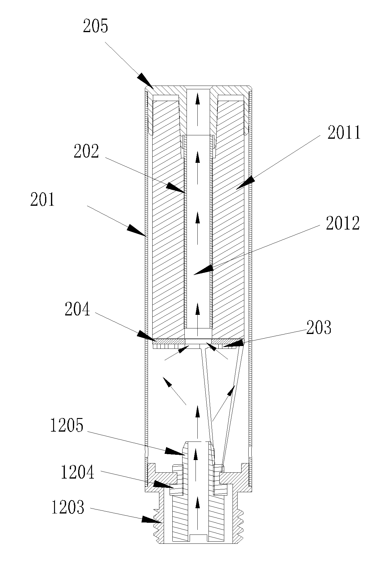
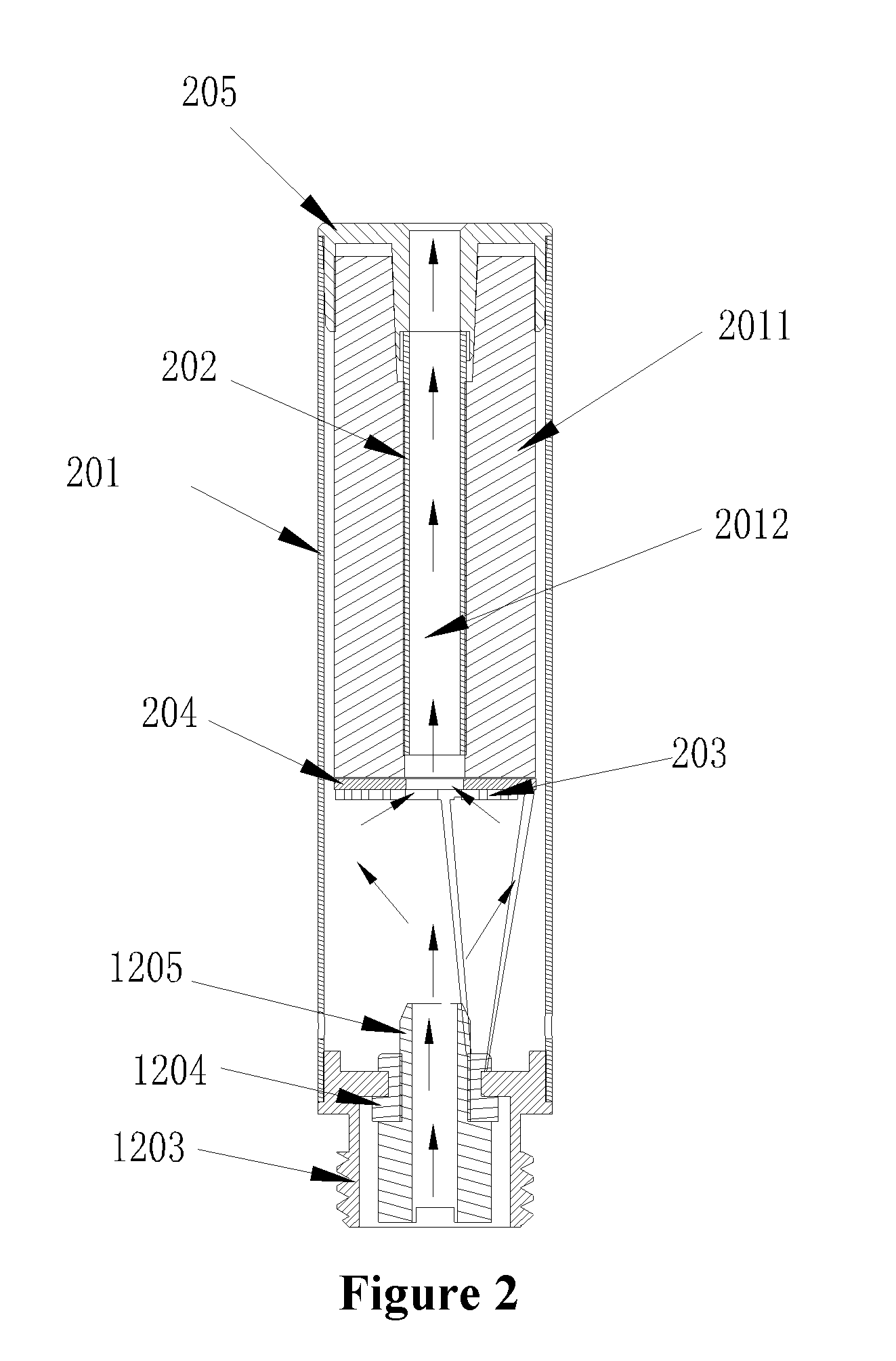
[0070]In a first embodiment, an atomizer is provided. Reference may be made to FIGS. 2 and 3 for a structure of the atomizer.
[0071]FIG. 2 is a schematic sectional of an atomizer provided in the present application, and FIG. 3 is a schematic exploded view showing a connection structure of the atomizer provided in the present application.
[0072]The atomizer includes: an atomizer cartridge 201, a liquid storage area 202, an electric heating element 203, and a first liquid guide cloth 204.
[0073]The liquid storage area 202 for storing a cigarette liquid is arranged inside the atomizer cartridge.
[0074]That is, the cigarette liquid can be sealedly stored inside the liquid storage area 202.
second embodiment
[0075]Specifically, reference may be made to a second embodiment for a specific structure of the liquid storage area 202, which is not described in this embodiment. The liquid storage area 202 may be in any structures so long as the liquid storage area can store therein the cigarette liquid.
[0076]The electric heating element 203 is for atomizing the cigarette liquid to generate smoke and is coiled spirally to form a plate-shape structure.
[0077]The electric heating element 203 is capable of atomizing the cigarette liquid to generate smoke which can be inhaled by a user.
[0078]Specifically, a plane where the electric heating element 203 locates may be perpendicular to or at a certain angle with respect to the axis of the atomizer cartridge 201.
[0079]For improving yield rate of products, facilitating the assembly and ensuring the volume of the smoke generated by atomization of the electric heating element 203 as large as possible, according to the embodiment, the plane where the electri...
third embodiment
[0121]In a third embodiment, the specific structure of the electric heating element 203 is described in detail.
[0122]The electric heating element 203 in the present application may be arranged with the following approaches.
[0123]Reference may be made to FIG. 4 for a first approach. Multiple sheet-like electric heating wires interconnected with each other are coiled to form the electric heating element 203 having a spiral sheet structure and the electric heating element is laid flat on the first liquid guide cloth 204, such that the electric heating element laid on the first liquid guide cloth 204 has a spiral structure. The spiral electric heating element 203 includes multiple interconnected spiral coils, and a gap 402, through which air or smoke can flow, is formed between any two interconnected spiral coils.
[0124]Reference may be made to FIG. 7 for a second approach. A flat metal block is directly punched to form an electric heating wire having a spiral sheet structure, and then t...
PUM
Abstract
An atomizer and an electronic cigarette are provided. The atomizer includes: an atomizer cartridge; a liquid storage area arranged inside the atomizer cartridge; an electric heating element coiled spirally to form a plate-shape structure; and a first liquid guide cloth. The first liquid guide cloth is arranged covering an opening of the liquid storage area, and the electric heating element is laid on a side of the first liquid guide cloth away from the liquid storage area. With the first liquid guide cloth, the quantity of the cigarette liquid transferred to the electric heating element is ensured to be equable. The electric heating element is arranged along the transverse direction of the atomizer, thereby avoiding conventional problems of non-uniform smoke volume and burning-out of the liquid storage cotton due to gravity or vibration of the spiral coils.
Description
CROSS-REFERENCED APPLICATIONS[0001]This application is the national phase of International Application No. PCT / CN2014 / 076004, titled “ATOMIZER AND ELECTRONIC CIGARETTE”, filed on Apr. 23, 2014, which claims the benefit of priority to Chinese Patent Application No. 201420161302.2, titled “ATOMIZER AND ELECTRONIC CIGARETTE”, filed with the State Intellectual Property Office of the PRC on Apr. 3, 2014, the entire disclosure of which are incorporated herein by reference.BACKGROUND[0002]1. Field of the Disclosure[0003]The present application relates to the technical field of electronic cigarettes, and particularly to an atomizer which effectively increases smoke volume and an electronic cigarette.[0004]2. Discussion of the Background Art[0005]Reference is made to FIG. 1 for the structure of a conventional atomizer. As illustrated in FIG. 1, the atomizer is for atomizing a cigarette liquid to generate a smoke for being inhaled by a user. In a specific arrangement, a glass fiber tube 102 i...
Claims
Application Information
Patent Timeline
Application Date:The date an application was filed.
Publication Date:The date a patent or application was officially published.
First Publication Date:The earliest publication date of a patent with the same application number.
Issue Date:Publication date of the patent grant document.
PCT Entry Date:The Entry date of PCT National Phase.
Estimated Expiry Date:The statutory expiry date of a patent right according to the Patent Law, and it is the longest term of protection that the patent right can achieve without the termination of the patent right due to other reasons(Term extension factor has been taken into account ).
Invalid Date:Actual expiry date is based on effective date or publication date of legal transaction data of invalid patent.

