Monitoring of a pressurized gas-based cleaning process in a hose filter installation

Inactive Publication Date: 2017-02-09
PRIMETALS TECH AUSTRIA GMBH
View PDF8 Cites 5 Cited by
  • Summary
  • Abstract
  • Description
  • Claims
  • Application Information

AI Technical Summary

Benefits of technology

The patent describes a method for monitoring a cleaning process using pressurized gas. This method allows for quick and reliable cleaning without the need for multiple valves and filters. The system also detects any malfunctions in the hose filter installation and alerts operators to prevent failure. Additionally, the system includes a warning system that alerts operators when the number of cleaning processes that can still be performed is low. A pressurized gas reservoir is also included in the hose filter installation to ensure a steady supply of gas for the cleaning process. Overall, this system improves the efficiency of cleaning processes and reduces downtime for maintenance.

Problems solved by technology

If the cleaning and / or an efficiency of the cleaning is impaired, e.g. due to a defect of an element of the hose filter installation, the exhaust gas throughput and the dedusting efficiency of the hose filter installation are reduced.
However, this monitoring method does not permit any conclusion concerning a mechanical state and / or a mechanical behavior of the valve or of further elements of the hose filter installation.
With this monitoring method, therefore, mechanical damage to the hose filter installation is not detected.
Furthermore, this monitoring method is complex / cost-intensive, because each valve has to be monitored individually.
Owing to a lack of objectivity of empirical values and of human perception, this monitoring method is not reliable.
In addition, this monitoring method involves a great expenditure of time / effort for the operating personnel, because a hose filter installation comprises a plurality of hose filters which must be monitored sequentially during an operation of the hose filter installation.
Furthermore, in many hose filter installations, it is prohibited, due to safety regulations, to enter these during operation, so that this monitoring method cannot be applied at all.
This monitoring method has the disadvantage that a plurality of such acoustic sensors and associated data lines is necessary for monitoring all of the hose filters.
Therefore, a system for carrying out this monitoring method is complex in its installation and also cost-intensive.
Indirectly, therefore, the monitoring method is also cost-intensive.

Method used


Image

  • Monitoring of a pressurized gas-based cleaning process in a hose filter installation
  • Monitoring of a pressurized gas-based cleaning process in a hose filter installation
  • Monitoring of a pressurized gas-based cleaning process in a hose filter installation

Examples


Embodiment Construction

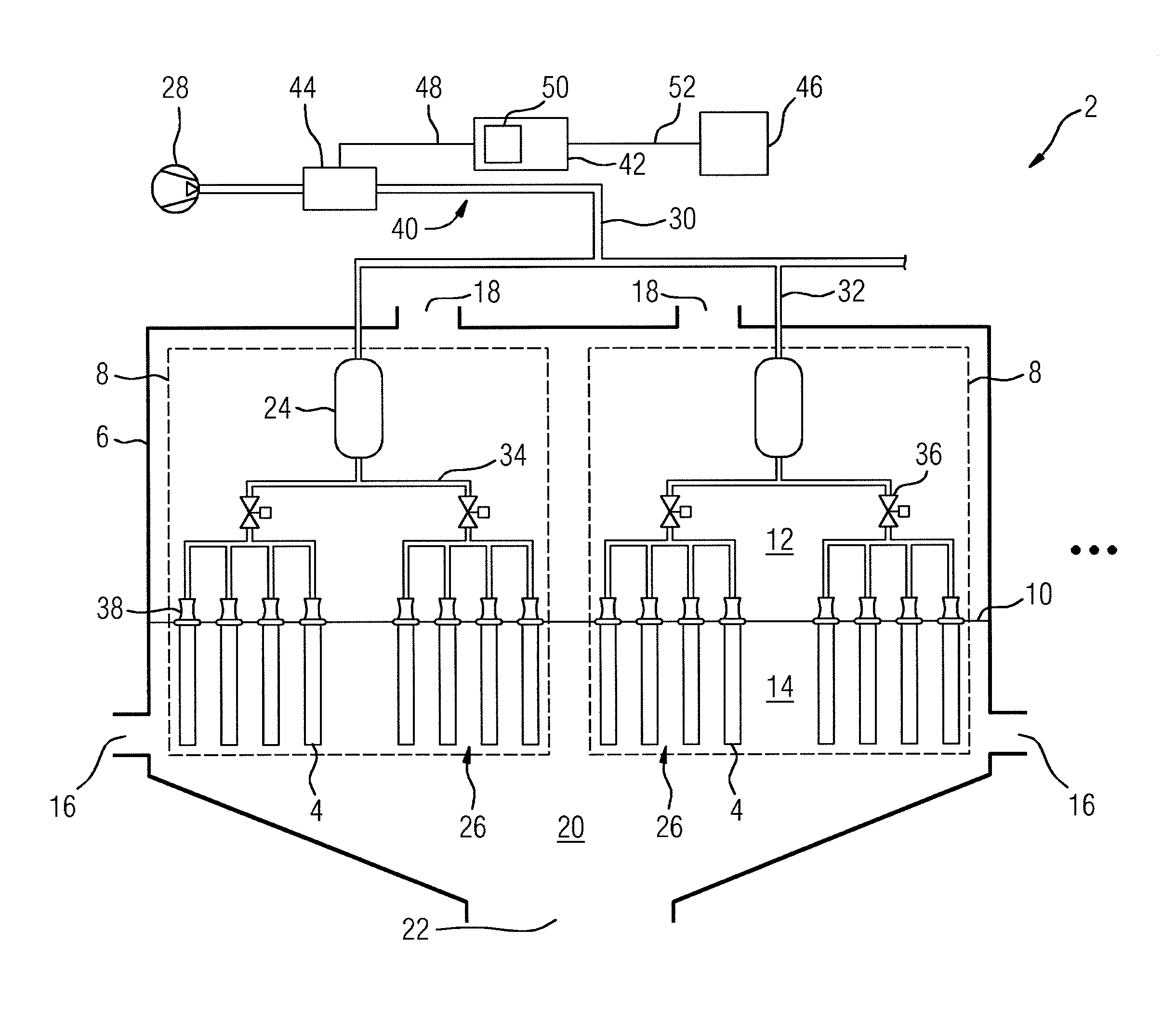
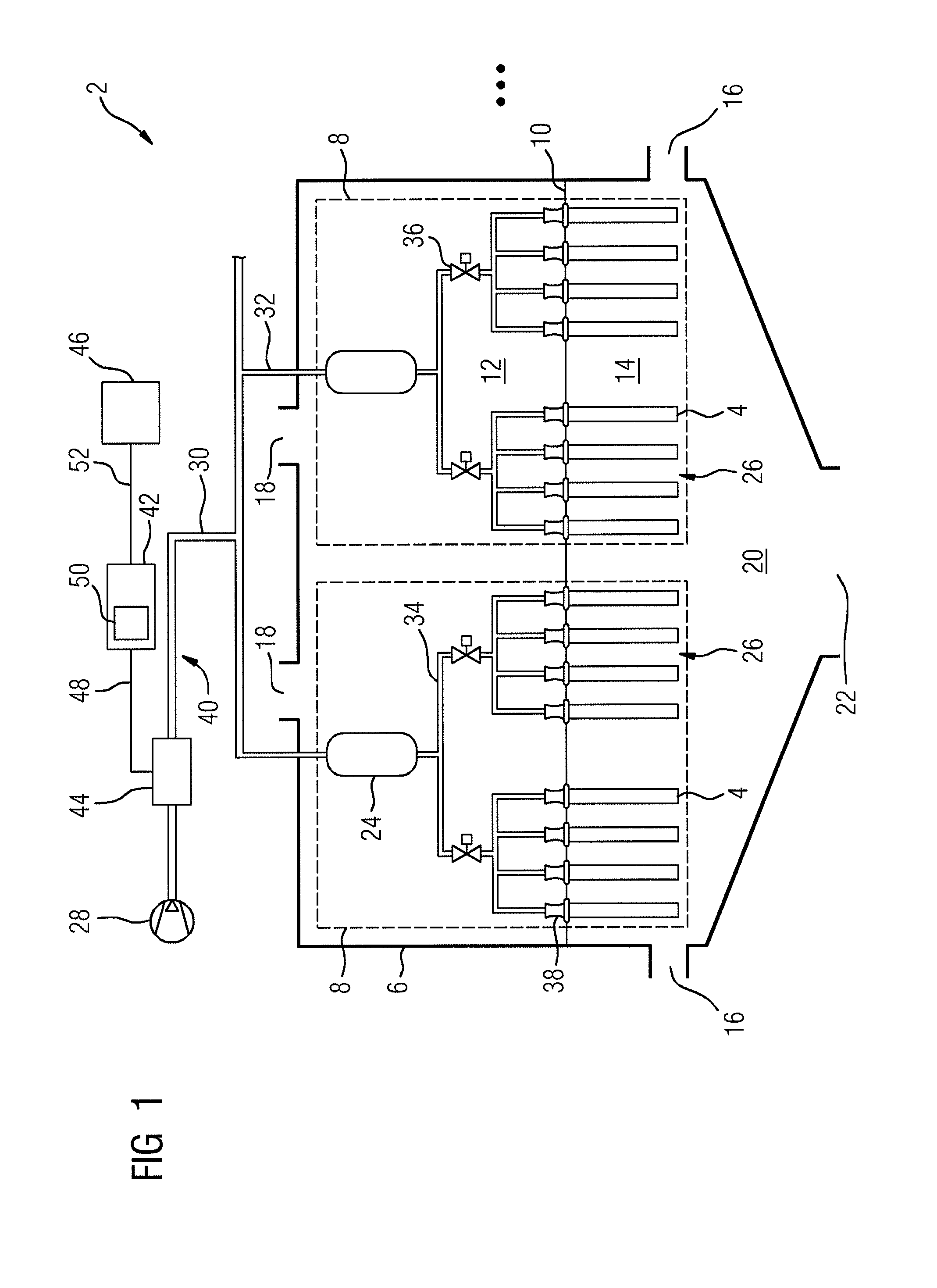
[0073]FIG. 1 shows diagrammatically a hose filter installation 2 with a plurality of hose filters 4. The hose filter installation 2 comprises several filter chambers 6, which in the present example are respectively divided into two chamber segments 8. Basically, it is also possible that the filter chambers 6 comprise respectively only one chamber segment 8 or are divided into more than two chamber segments 8. For the sake of clarity, in FIG. 1 only one of the several filter chambers 6 is illustrated by way of example.

[0074]In each of the filter chambers 6 respectively a perforated plate 10 is arranged, at the holes of which the hose filters 4 are arranged, and which divides the filter chamber 6 into a clean gas space 12 and a crude gas space 14. The crude gas space 14 contains an exhaust gas which is to be cleaned in a dust-containing state, whereas the clean gas space 12 contains the exhaust gas after its dedusting, i.e. in a substantially dust-free state.

[0075]The filter chambers ...


PUM

PropertyMeasurementUnit
Pressureaaaaaaaaaa
Massaaaaaaaaaa
Volumeaaaaaaaaaa

Abstract

A method for monitoring a pressurized gas-based cleaning process in a hose filter installation (2): during a cleaning process, a throughflow (Q) of a pressurized-gas flow during a predefinable time period (T) is determined, a throughflow characteristic (V) is determined using the determined throughflow (Q) of the pressurized-gas flow, and the pressurized gas-based cleaning process is monitored using the throughflow characteristic (V), wherein the throughflow characteristic (V) is a pressurized-gas quantity that has flowed in the predefinable time period (T). A monitoring system (40) for a hose filter installation (2) has at least one throughflow sensor (44) for determining a throughflow (Q) of a pressurized-gas flow, and a control unit (42) for controlling a pressurized gas-based cleaning process, wherein the throughflow sensor (44) is a volume flow sensor or a mass flow sensor, and the control unit (42) is set up for carrying out the method.

Description

CROSS-REFERENCE TO RELATED APPLICATIONS[0001]The present application is a 35 U.S.C. §§371 national phase conversion of PCT / EP2015 / 056177, filed Mar. 24, 2015, which claims priority of European Patent Application No. 14166050.6, filed Apr. 25, 2014, the contents of which are incorporated by reference herein. The PCT International Application was published in the German language.[0002]The invention relates to a method for monitoring a pressurized gas-based cleaning process in a hose filter installation. The invention further relates to a monitoring system for a hose filter installation, having at least one throughflow sensor for determining a throughflow of a pressurized gas flow and a control unit for controlling a pressurized gas-based cleaning process. The invention furthermore relates to a hose filter installation with a plurality of hose filters.TECHNICAL BACKGROUND[0003]In several industrial processes, in particular in metallurgical processes, exhaust gases are produced, which c...

Claims


Application Information

Patent Timeline
IPC IPC(8): B01D46/00B01D46/44
CPCB01D46/444B01D46/0068B01D46/71
Inventor LAUTERBRUNNER, HERBERTLEHOFER, MARTINMAIR, STEFANROHRHOFER, ANDREAS
Owner PRIMETALS TECH AUSTRIA GMBH
Why Eureka
Try Eureka