Vehicle height adjustment device
a height adjustment and vehicle technology, applied in the direction of cycle equipment, transportation and packaging, cycle, etc., can solve the problem of difficulty in making the height of the vehicle the target valu
- Summary
- Abstract
- Description
- Claims
- Application Information
AI Technical Summary
Benefits of technology
Problems solved by technology
Method used
Image
Examples
first embodiment
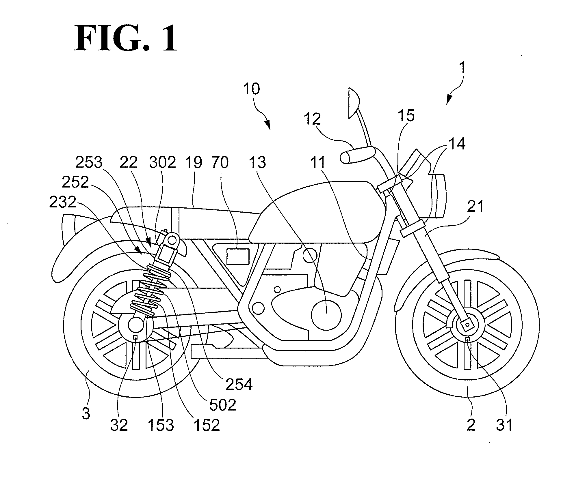
[0030]FIG. 1 illustrates a schematic configuration of a motorcycle 1 according to a first embodiment.
[0031]The motorcycle 1 includes a front wheel 2, a rear wheel 3, and a body 10. The front wheel 2 is a wheel on the front side of the motorcycle 1. The rear wheel 3 is a wheel on the rear side of the motorcycle 1. The body 10 includes elements such as a frame 11, a handle 12, an engine 13, and a seat 19. The frame 11 defines the framework of the motorcycle 1.
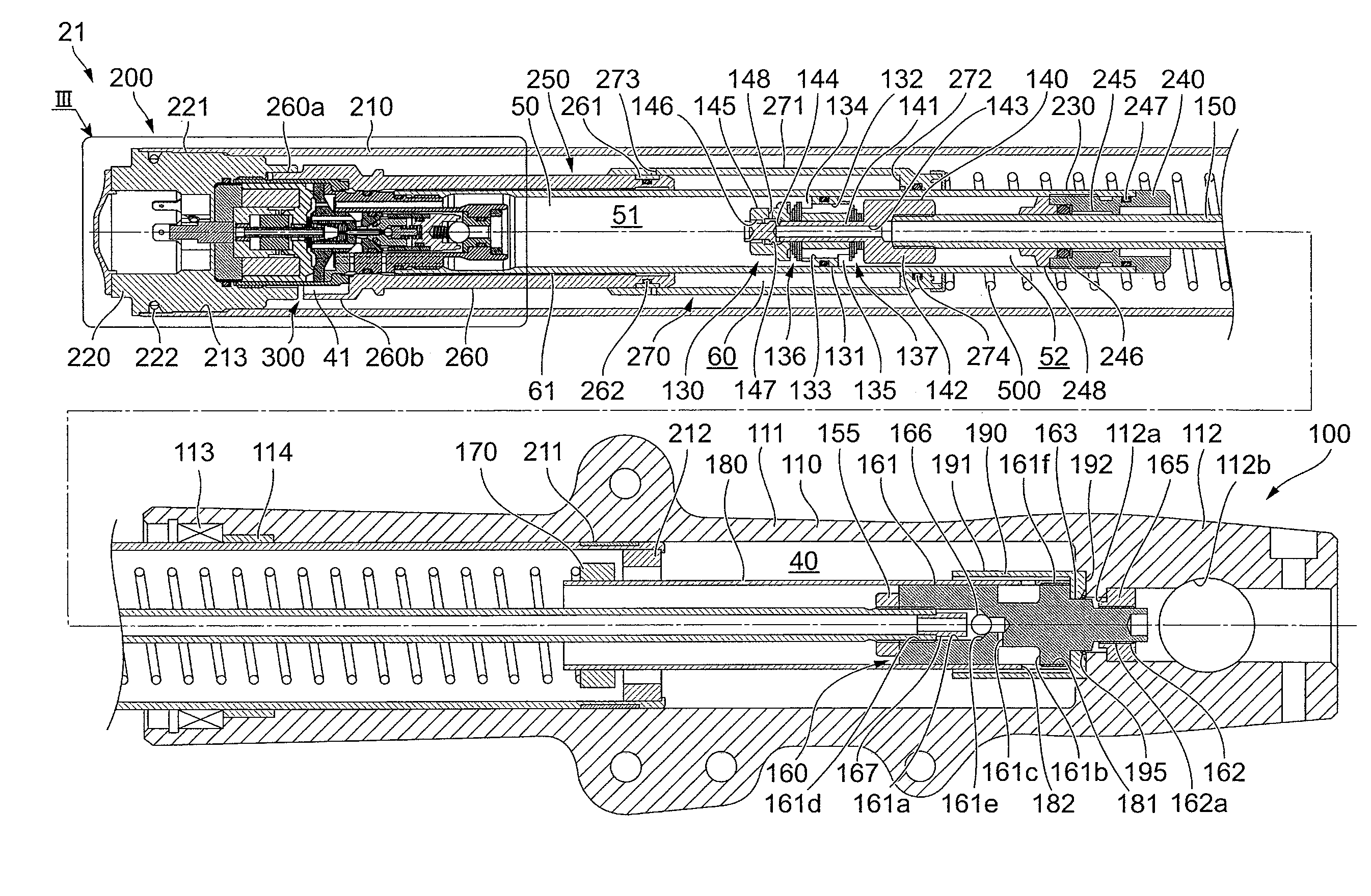
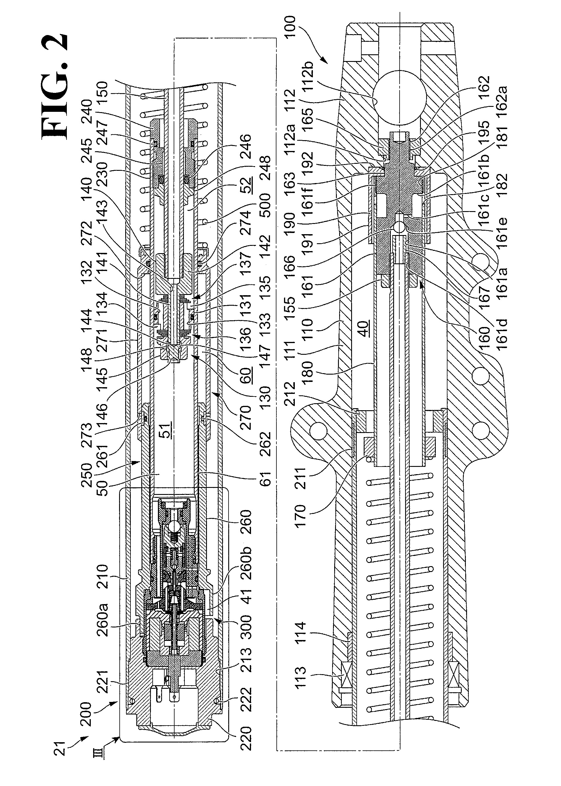
[0032]The motorcycle 1 includes front forks 21, which are an example of a suspension device that couples the front wheel 2 and the body 10 to each other. The motorcycle 1 also includes rear suspensions 22 to couple the rear wheel 3 and the body 10 to each other. The front forks 21 and the rear suspensions 22 are an example of the changer to change the position of the body 10 relative to the axle of the front wheel 2 and the position of the body 10 relative to the axle of the rear wheel 3.
[0033]The motorcycle 1 includes two bracke...
second embodiment
[0248]The motorcycle 1 according to a second embodiment is different from the motorcycle 1 according to the first embodiment in the front-wheel target current determiner 711.
[0249]A control map according to the second embodiment illustrating correspondence between the front-wheel displacement amount deviation ΔLf and the front-wheel target current Itf is the same as the control map according to the first embodiment illustrated in FIG. 14, which shows the correspondence between the front-wheel displacement amount deviation ΔLf and the front-wheel target current Itf. In other words, the control map illustrated in FIG. 14, which shows the correspondence between the front-wheel displacement amount deviation ΔLf and the front-wheel target current Itf, is also the control map according to the second embodiment illustrating correspondence between the front-wheel displacement amount deviation ΔLf and the front-wheel target current Itf.
[0250]Differences of the motorcycle 1 according to the s...
third embodiment
[0262]The motorcycle 1 according to a third embodiment is different from the motorcycle 1 according to the first embodiment in the control map illustrating correspondence between the front-wheel displacement amount deviation ΔLf and the front-wheel target current Itf. Differences of the motorcycle 1 according to the third embodiment from the motorcycle 1 according to the first embodiment will be mainly described below.
[0263]FIG. 17 is a graph of a control map according to the third embodiment schematically illustrating the correspondence between the front-wheel displacement amount deviation ΔLf and the front-wheel target current Itf.
[0264]In the control map according to the third embodiment illustrated in FIG. 17, in an area in which the front-wheel displacement amount deviation ΔLf is positive (plus), the front-wheel target current Itf is set to be zero when the front-wheel displacement amount deviation ΔLf is equal to or smaller than the front-wheel first reference deviation ΔLf1 ...
PUM
 Abstract
Description
Claims
Application Information
 - R&D
- Intellectual Property
- Life Sciences
- Materials
- Tech Scout
- Unparalleled Data Quality
- Higher Quality Content
- 60% Fewer Hallucinations
Browse by: Latest US Patents, China's latest patents, Technical Efficacy Thesaurus, Application Domain, Technology Topic, Popular Technical Reports.
© 2025 PatSnap. All rights reserved.Legal|Privacy policy|Modern Slavery Act Transparency Statement|Sitemap|About US| Contact US: help@patsnap.com


