
Driving-force control device for vehicle

a technology of driving force control and control device, which is applied in the direction of propulsion parts, propulsion using engine-driven generators, transportation and packaging, etc., can solve the problem of being unable to carry out sprung vibration suppression control while performing free run, and achieve the effect of low need for sprung vibration suppression control, increased braking torque, and free run

Active Publication Date: 2017-02-09
TOYOTA JIDOSHA KK
View PDF4 Cites 12 Cited by
  • Summary
  • Abstract
  • Description
  • Claims
  • Application Information

AI Technical Summary

Benefits of technology

The present invention relates to a technology for reducing vibration and gear rlide in a vehicle during operation. The technology includes a target torque adjustment means that adjusts the target torque based on the magnitude of the vibration suppression control torque. By doing so, the technology can properly carry out sprung vibration suppression control without causing excessive deceleration of the vehicle. Additionally, the technology can estimate the extent of the vehicle body vertical vibration and prevent changes in the target torque due to temporary changes in road conditions. This reduces discomfort for the driver and improves the overall performance of the vehicle.

Problems solved by technology

Therefore, in the device proposed in the Patent Document 1, it becomes impossible to carry out sprung vibration suppression control while performing free run.

Method used


Image

  • Driving-force control device for vehicle
  • Driving-force control device for vehicle
  • Driving-force control device for vehicle

Examples


Embodiment Construction

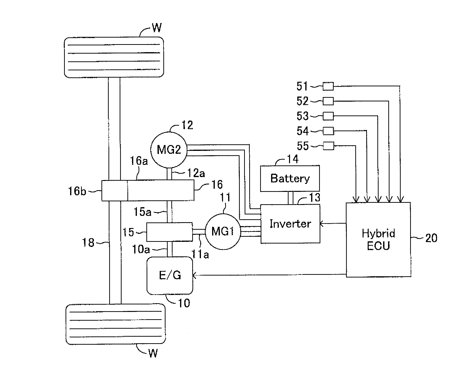
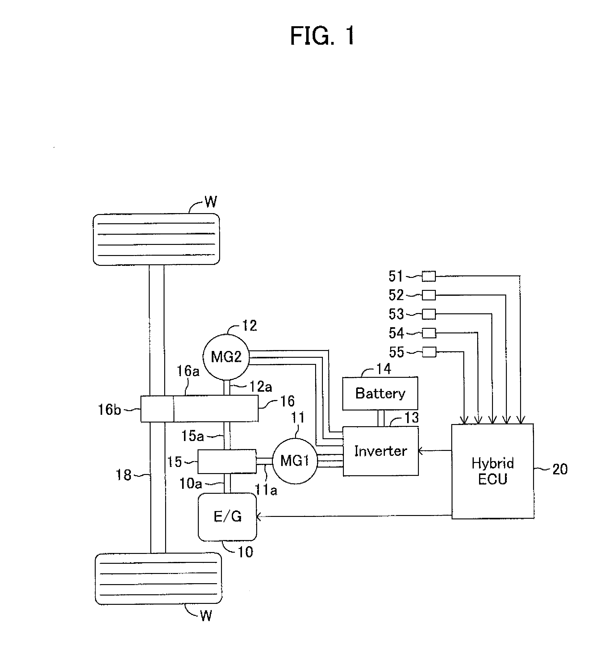
[0048]Hereafter, the embodiments of the present invention will be explained in detail using drawings. FIG. 1 schematically shows the configuration of a driving-force control device for a vehicle according to the present embodiment.

[0049]A vehicle on which this driving-force control device is mounted is a hybrid vehicle. The driving-force control device comprises an engine 10, a first motor-generator 11 (referred to as a first MG11), a second motor-generator 12 (referred to as a second MG12), an inverter 13, a battery 14, a motive-power distribution mechanism 15, a driving-force transmission mechanism 16, and a hybrid ECU20. In addition, ECU is the abbreviation for Electric Control Unit. Although the vehicle on which the driving-force control device according to the present embodiment is mounted is a rear-drive vehicle, it may be a front-wheel-drive vehicle or a four-wheel-drive vehicle.

[0050]Although the engine 10 is a gasoline engine, it may be a diesel engine.

[0051]The motive-powe...


PUM


Abstract

In a situation where it is predicted that a symbol of target torque reverses by turns to be positive and negative alternately, the hybrid ECU carries out an increasing correction of the target torque, in which the target torque is corrected by increasing the target torque by a set amount ΔT in a negative direction when a specific condition, in which it is judged that the degree of the vertical vibration of a vehicle body is larger than a standard value and it is judged there is no acceleration demand, is satisfied, and makes the vibration suppression control torque not to be contained in the target torque when the specific condition is not satisfied. Thereby, even when carrying out free run, the sprung vibration suppression control can be carried out during bad road running, and braking force can be suppressed and fuel consumption can be improved during good road running.

Description

TECHNICAL FIELD[0001]The present invention relates to a driving-force control device for a vehicle, which carries out sprung vibration suppression control (damping control) that is control in which vibration of a sprung mass of the vehicle (sprung vibration) is reduced.BACKGROUND ART[0002]Conventionally, sprung vibration suppression control in which sprung vibration is reduced by controlling torque of a driving source for running that drives a wheel has been known. For example, in a device proposed in the Patent Document 1 (PTL1), target torque which is obtained by adding vibration suppression control torque for suppressing vibration of a sprung mass to basic demand torque demanded for carrying out acceleration and / or deceleration of a vehicle is generated in a driving source for running. A symbol of the vibration suppression control torque alternately changes to be positive and negative, according to the vibration of the sprung mass. That is, the vibration suppression control torqu...

Claims


Application Information

Patent Timeline
IPC IPC(8): B60W20/15B60W20/40B60W20/11B60L50/16
CPCB60W20/15B60W20/11B60W20/40B60W2510/244B60W2710/0666B60W2520/105B60W2520/10B60W2710/083B60W10/06B60W10/08B60W30/02B60W40/00B60W2050/0043B60W2050/0014B60K6/445B60W30/025Y02T10/62Y02T10/72
Inventor KANOU, TAKESHINARUSE, TOMOHIROSEKIYA, YOSHIHIDEYAMAGATA, YU
Owner TOYOTA JIDOSHA KK
Learn More