Cryogenic fluid circuit design for effective cooling of an elongated thermally conductive structure extending from a component to be cooled to a cryogenic temperature

a thermally conductive structure and circuit design technology, applied in the direction of superconducting magnets/coils, refrigeration devices, lighting and heating apparatus, etc., can solve the problems of significant heat leakage into the core of the system, difficult design of cryogenic apparatus for use below 70 degrees kelvin, etc., to reduce the cryogenic base temperature of the system, reduce the heat load, and reduce the heat load

Inactive Publication Date: 2017-02-09
VICTORIA LINK LTD
View PDF8 Cites 31 Cited by
  • Summary
  • Abstract
  • Description
  • Claims
  • Application Information

AI Technical Summary

Benefits of technology

[0008]The disclosed embodiments involve an effective and adjustable method of tailoring the degree of cooling applied to an elongated thermally conductive structure extending from a component in a cryogenic chamber to the external environment in order to reduce the he

Problems solved by technology

The properties of common materials often change when the materials are cooled to a cryogenic temperature, and these changes complicate the design of cryogenic apparatus.
The design of cryogenic apparatus for use below 70 degrees Kelvin is particularly difficult, because just a few elements have boiling points below 70 degrees Kelvin.
A common problem in cryogenic system design is the

Method used


Image

  • Cryogenic fluid circuit design for effective cooling of an elongated thermally conductive structure extending from a component to be cooled to a cryogenic temperature
  • Cryogenic fluid circuit design for effective cooling of an elongated thermally conductive structure extending from a component to be cooled to a cryogenic temperature
  • Cryogenic fluid circuit design for effective cooling of an elongated thermally conductive structure extending from a component to be cooled to a cryogenic temperature

Examples


Embodiment Construction

[0020]It will be appreciated that for simplicity and clarity of illustration, where appropriate, reference numerals have been repeated among the different figures to indicate corresponding or analogous elements. In addition, numerous specific details are set forth in order to provide a thorough understanding of the embodiments described herein. However, it will be understood by those of ordinary skill in the art that the embodiments described herein can be practiced without these specific details. In other instances, methods, procedures and components have not been described in detail so as not to obscure the related relevant feature being described. Also, the description is not to be considered as limiting the scope of the embodiments described herein. The drawings are not necessarily to scale and the proportions of certain parts have been exaggerated to better illustrate details and features of the present disclosure.

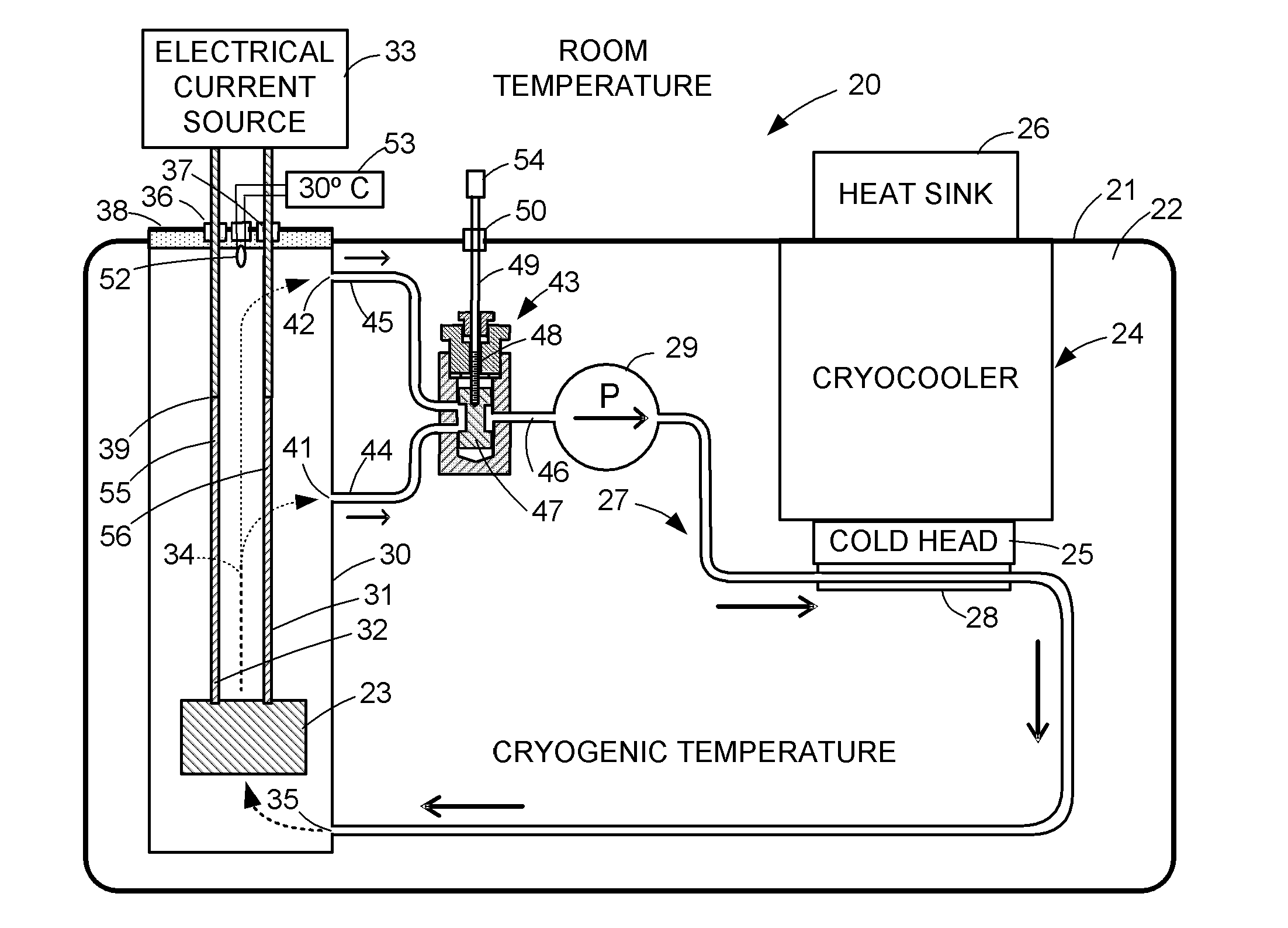
[0021]FIG. 1 shows a cryogenic system 20 including a housing 21 ...


PUM


Abstract

A cryogenic system includes a housing of a cryogenic chamber, a cold source in the cryogenic chamber, and a circulation loop for circulating cryogenic fluid between the cold source and a component to be cooled in the cryogenic chamber. The component has an elongated thermally conductive structure extending to a warmer environment. For adjustable cooling of the structure, an incoming stream of the cryogenic fluid is directed along a length of the structure extending from the component, and this stream is split into a first outgoing stream at a first location from the component and a second outgoing stream at a second location further from the component, and an adjustable valve adjusts the fraction of the incoming stream that becomes the second outgoing stream.

Description

TECHNICAL FIELD[0001]This disclosure relates to circulation of cryogenic fluid in a cryogenic system, and a fluid circuit design for effective cooling of an elongated thermally conductive structure that extends from a component that is being cooled to a warmer environment. Such structures may include but are not limited to current leads, mechanical supports, mechanical feedthroughs, and rotational bearings.BACKGROUND ART[0002]The properties of common materials often change when the materials are cooled to a cryogenic temperature, and these changes complicate the design of cryogenic apparatus. These changes become substantial below a temperature of about 150 degrees Kelvin. Therefore, in this disclosure, “cryogenic” relates to a temperature below 150 degrees Kelvin. For example, “cryogenic gas” is a gas of a material that has a boiling point below 150 degrees Kelvin, and “cryogenic fluid” is a gas of a material that has a boiling point below 150 degrees Kelvin or a liquid of a materi...

Claims


Application Information

Patent Timeline
IPC IPC(8): F25D19/00H01F6/04F25D29/00F25B9/00F25B9/10
CPCF25D19/00F25B9/00H01F6/04F25D29/001F25B9/10
Inventor STRICKLAND, NICHOLASWIMBUSH, STUART
Owner VICTORIA LINK LTD
Why Eureka
Try Eureka