Modular assembly for a turbine engine

a technology of turbine engines and modules, which is applied in the direction of engines, machines/engines, turbine/propulsion lubrication, etc., can solve the problems of reducing the pumping range of hp compressors, too restrictive, damage to the teeth of pinions,

Active Publication Date: 2017-02-16
SN DETUDE & DE CONSTR DE MOTEURS DAVIATION S N E C M A
View PDF8 Cites 13 Cited by
  • Summary
  • Abstract
  • Description
  • Claims
  • Application Information

AI Technical Summary

Problems solved by technology

Studies have shown that an additional take-off of power from the HP shaft reduces the pumping range of the HP compressor and could be too restrictive from a performance and operability point of view.
This architecture has some disadvantages related to the fittin

Method used


Image

  • Modular assembly for a turbine engine
  • Modular assembly for a turbine engine
  • Modular assembly for a turbine engine

Examples


Embodiment Construction

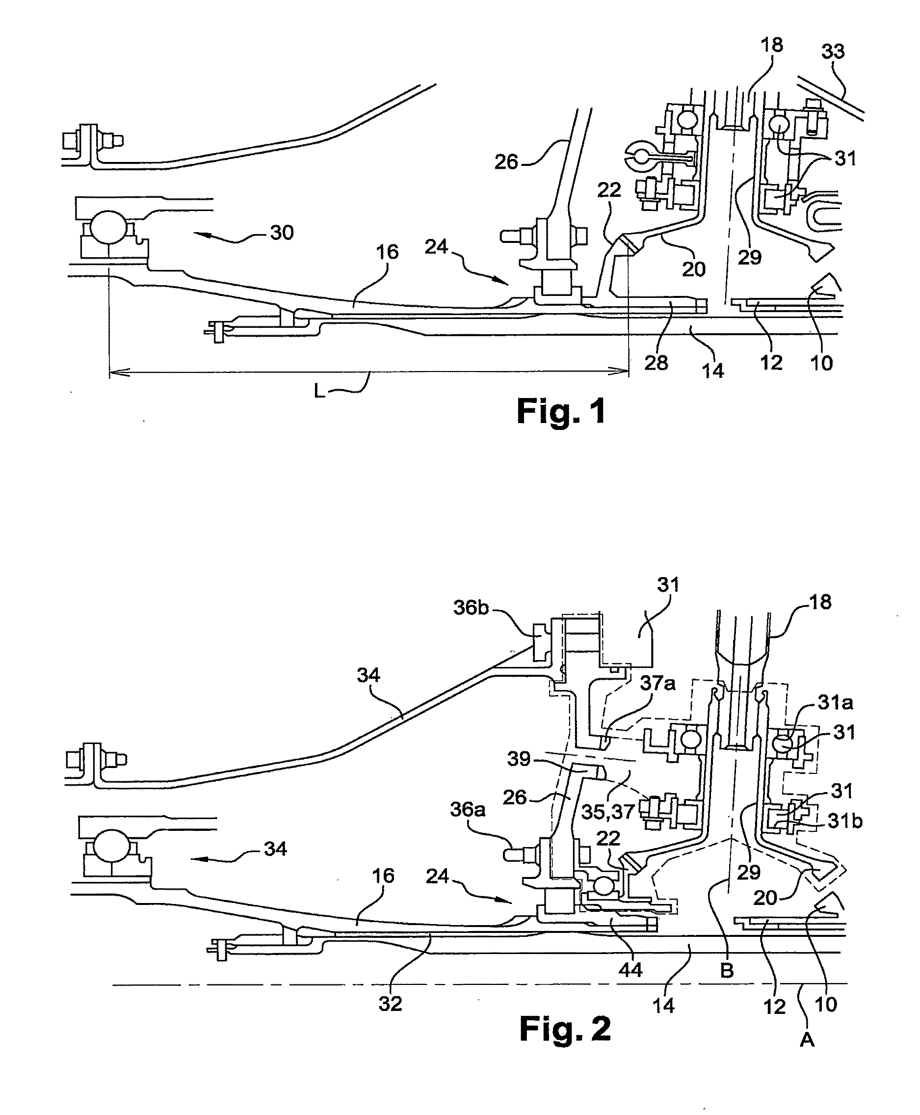
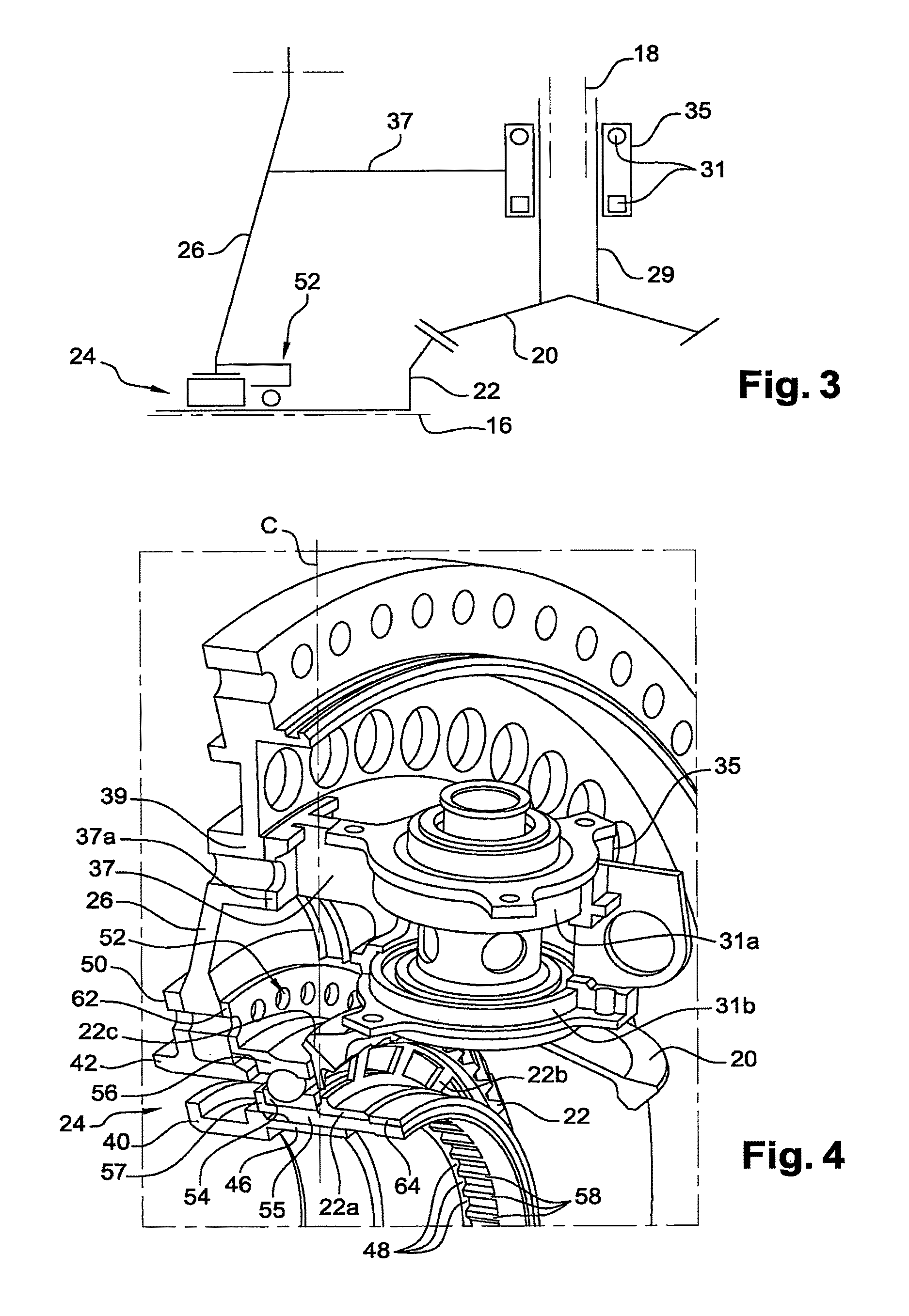
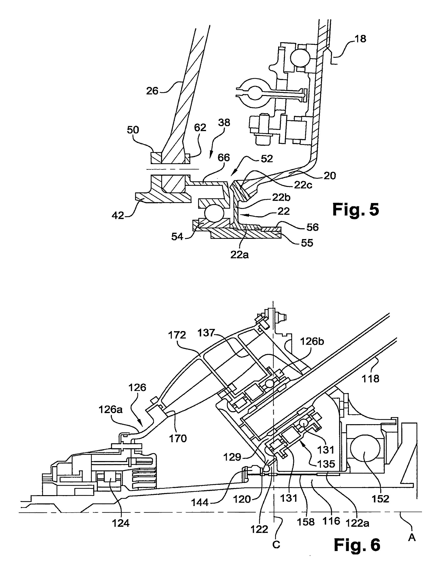
[0020]For this purpose, the invention proposes a modular assembly for a turbine engine, comprising a fan shaft, fan shaft guide bearings, and an annular bearing support, said annular support comprising means for connection to at least a first anti-friction bearing fitted around said fan shaft, characterised in that said annular support comprises means for connection to at least a second anti-friction bearing configured to be fitted around a second shaft of the turbine engine not parallel to said first shaft, and in that said annular support comprises means for connection to an intermediate casing of the turbine engine.

[0021]The invention makes it possible in particular to simplify the fitting of a turbine engine for which modular or en bloc fitting is permitted.

[0022]The modular assembly according to the invention can comprise one or more than one of the following features, taken separately from one another or in combination with one another:[0023]said bearing support comprises mean...


PUM


Abstract

A modular assembly for a turbine engine has an annular bearing support that is configured to be connected to a first anti-friction bearing, which is configured to be fitted around a first shaft of the turbine engine. The modular assembly further includes a second anti-friction bearing configured to be fitted around a second shaft of the turbine engine, wherein the second shaft is not parallel to said first shaft.

Description

TECHNICAL FIELD[0001]The present invention relates to a modular assembly for a turbine engine, in particular of an aircraft.PRIOR ART[0002]A turbine engine comprises an engine which, in the case of a double-body turbojet engine, has two shafts, low pressure (LP) and high pressure (HP) respectively, which extend along the longitudinal axis of the turbine engine. The LP and HP shafts are generally tubular and fitted one inside the other.[0003]Driving an item of equipment of the turbine engine using a substantially radial (relative to the longitudinal axis of the turbine engine) countershaft has already been proposed. This is the case in particular when the item of equipment is fitted in a nacelle that surrounds the engine of the turbine engine. The countershaft transmits mechanical power between a shaft of the turbine engine and an item of equipment such as an accessory gear box (AGB). This countershaft is driven in rotation through a set of bevel pinions or gears. A countershaft beve...

Claims


Application Information

Patent Timeline
IPC IPC(8): F02C7/32F02C7/06F02C7/36F01D25/16
CPCF02C7/32F01D25/162F05D2240/90F02C7/36F05D2230/60F02C7/06F05D2230/72F05D2260/4031F01D25/16
Inventor CURLIER, AUGUSTINLEMARCHAND, KEVIN MORGANENOWAKOWSKI, NATHALIEVINCENT, THOMAS ALAIN CHRISTIAN
Owner SN DETUDE & DE CONSTR DE MOTEURS DAVIATION S N E C M A
Why Eureka
Try Eureka