Voltage Stability Monitoring Device and Method

a voltage stability and monitoring device technology, applied in measurement devices, measurement using digital techniques, instruments, etc., can solve the problems of power flow through existing transmission lines, power liberalization, and suppression of facility investment in power systems, so as to reduce the efforts of operators and accurately monitor the

Active Publication Date: 2017-02-16
HITACHI LTD
View PDF3 Cites 15 Cited by
  • Summary
  • Abstract
  • Description
  • Claims
  • Application Information

AI Technical Summary

Benefits of technology

[0012]According to the present invention, an assumed change scenario in which an output change of renewable energy is considered is automatically calculated, and thus, efforts of an operator are reduced. In addition, voltage stability monitoring calculation is performed with respect to the assumed change scenario, and thus, a bus in which deterioration of current or future voltage stability occurs varies dynamically, and the deterioration of the current or future voltage stability can be accurately monitored.

Problems solved by technology

In addition, recently, power liberalization has been proceeded in the world, and as a result, facility investment of the power system is suppressed, and a power flow flowing through an existing transmission line increases (becomes a heavy tide).
If tide variation (tide change) increases in a heavy tide state, voltage stability of a power system can deteriorate.
Furthermore, if the system fails due to lightning strike or the like, voltage stability of the power system can further deteriorate.

Method used


Image

  • Voltage Stability Monitoring Device and Method
  • Voltage Stability Monitoring Device and Method
  • Voltage Stability Monitoring Device and Method

Examples


embodiment 1

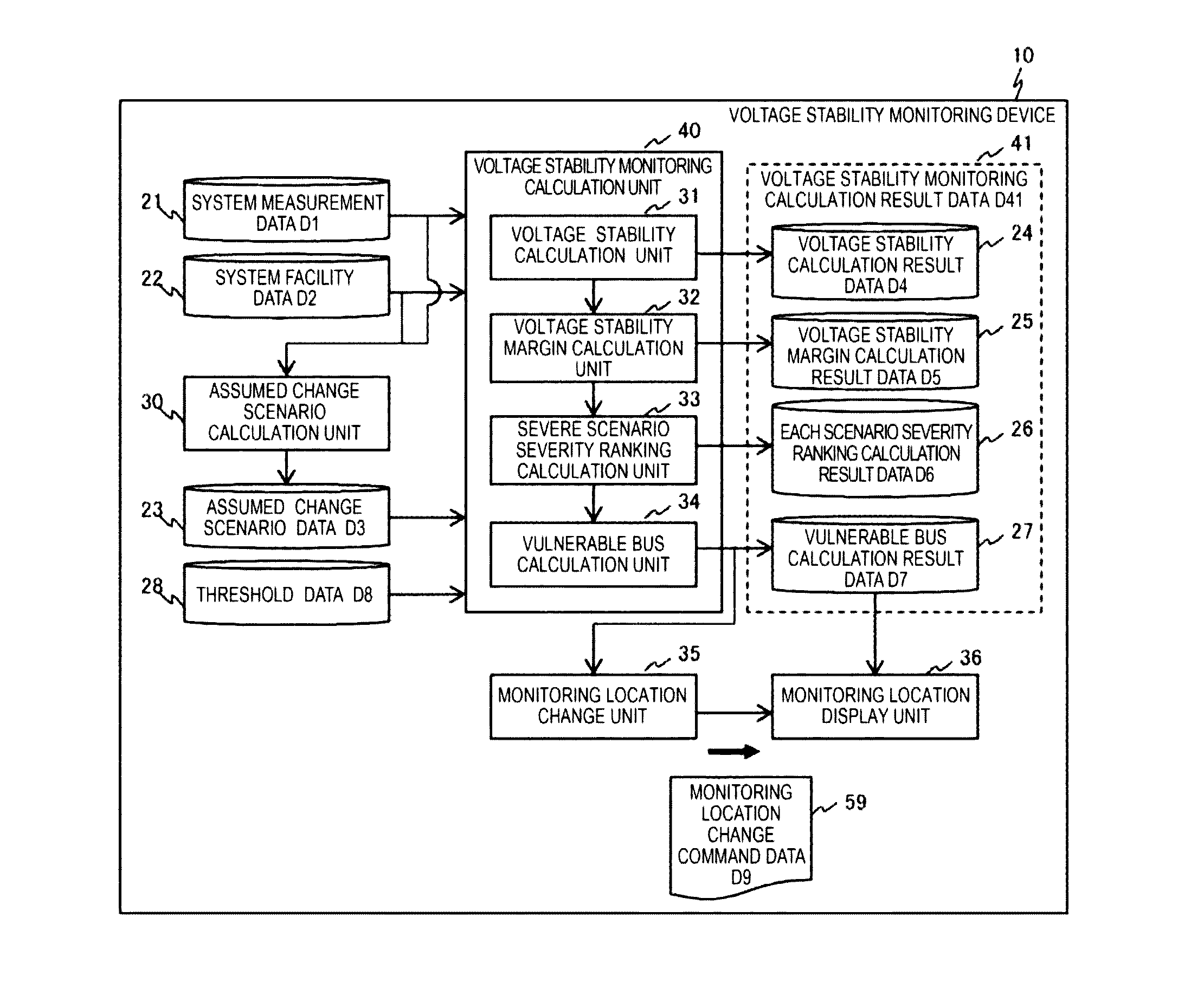
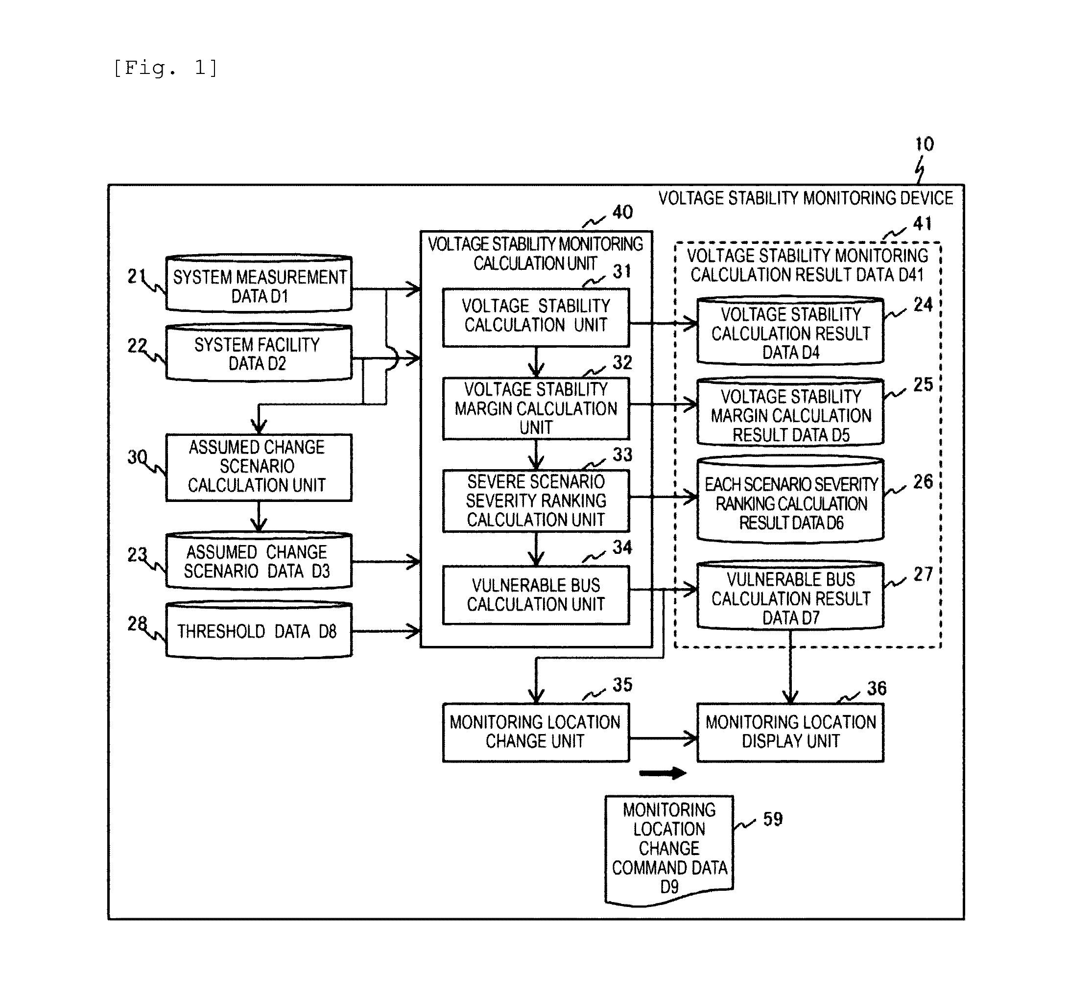
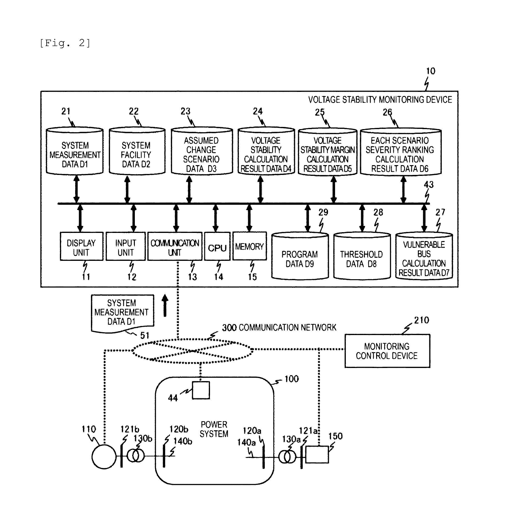
[0040]The present embodiment is an example of a voltage stability monitoring device 10 which performs each scenario severity ranking calculation and vulnerable bus calculation, outputs monitoring location change command data D9, and performs monitoring location display, based on results which are obtained by calculating an assumed change scenario from system data D1 and system facility data D2 and performing voltage stability calculation and voltage stability margin calculation, using the calculated assumed change scenario data D3, the system data D1, the system facility data D2, and threshold data D8. An example of an entire configuration that is configured with input and output in which a database and data show content and processing in which a calculation unit shows content is illustrated in FIG. 1. Subsequently, an example of a hardware configuration of a power system 100, a monitoring control device 210, the voltage stability monitoring device 10, a measurement device 44, a pow...

embodiment 2

[0109]The present embodiment describes an example of the voltage stability monitoring device in which it is determined whether a vulnerable bus is an accurate vulnerable bus based on restriction data D10 and is not a vulnerable bus obtained by simply performing vulnerable bus calculation, voltage stability calculation to which the restriction data is added is performed, and thus, an accurate vulnerable bus calculation is performed, in the vulnerable bus calculation of Embodiment 1. Descriptions on content which overlaps the content described in FIG. 1 to FIG. 22 will be omitted.

[0110]FIG. 23 is an example of an entire configuration diagram of the voltage stability monitoring device 10 according to Embodiment 2, and is configured by a device in which the restriction data D10 is added to the example of the entire configuration diagram of the voltage stability monitoring device 10 according to Embodiment 1 illustrated in FIG. 1. In the voltage stability monitoring device 10 in FIG. 23,...

embodiment 3

[0116]The present embodiment described an example of the voltage stability monitoring device which can transmit not only the voltage stability monitoring of Embodiment 1 but also the voltage stability monitoring result data D41 to an external monitoring control device. Description on content which overlaps the content described in FIG. 1 to FIG. 22 will be omitted.

[0117]FIG. 26 is an example of an entire configuration diagram of a voltage stability monitoring device, to which threshold data, a data transmission unit, and a monitoring control device are added with respect to FIG. 1 of Embodiment 1, according to Embodiment 3. In the voltage stability monitoring device 10 of FIG. 26, description on the configuration to which the same symbols or reference numerals as those illustrated in FIG. 1 previously described are attached, and portions having the same function will be omitted. A function of transmitting the voltage stability monitoring calculation result data D41 which is calculat...


PUM


Abstract

An object is to accurately monitor deterioration of current or future voltage stability, by dynamically changing a bus in which current or future voltage stability deteriorates, in stability monitoring calculation of a power system. Hence the present invention provides a voltage stability monitoring device, which monitors voltage stability of a power system, including an assumed change scenario calculation unit which produces a plurality of assumed change scenarios indicating a scenario of a change that is assumed based on at least one of a system configuration of the power system and a change of a tide state; a voltage stability calculation unit which calculates the voltage stability using the assumed change scenario; a voltage stability margin calculation unit which calculates a voltage stability margin indicating margin degree of the voltage stability, based on the voltage stability; an each scenario severity ranking calculation unit which selects an assumed change scenario with high severity of the voltage stability for each assumed change scenario, based on the voltage stability margin; a vulnerable bus calculation unit which calculates which of buses in the power system is a vulnerable bus that decreases voltage stability, based on the assumed change scenario which is selected; and a monitoring location change unit which changes a monitoring target of the voltage stability, based on information of the vulnerable bus.

Description

TECHNICAL FIELD[0001]The present invention relates to a voltage stability monitoring device which monitors voltage stability (also referred to as voltage stableness) of a power system.BACKGROUND ART[0002]In future, in addition to renewable energy (solar power generation, wind power generation, or the like), lots of power supplies (output variation type power supplies) whose outputs fluctuate depending upon weather are expected to be employed in large quantity in a power system. In addition, recently, power liberalization has been proceeded in the world, and as a result, facility investment of the power system is suppressed, and a power flow flowing through an existing transmission line increases (becomes a heavy tide). If tide variation (tide change) increases in a heavy tide state, voltage stability of a power system can deteriorate. Furthermore, if the system fails due to lightning strike or the like, voltage stability of the power system can further deteriorate. It is necessary t...

Claims


Application Information

Patent Timeline
Patent Type & Authority Applications(United States)
IPC IPC(8): G01R19/25G01R19/00
CPCG01R19/0084G01R19/2513H02J3/00H02J3/24H02J13/00H02J13/00034
Inventor KURODA, EISUKESATO, YASUOTOMOBE, OSAMUYAMAZAKI, JUNYATSU, MASAHIROHARA, KOUICHIMIYOSHI, HARUKI
Owner HITACHI LTD
Why Eureka
Try Eureka