
Sound signal processing device, sound signal processing method, and program

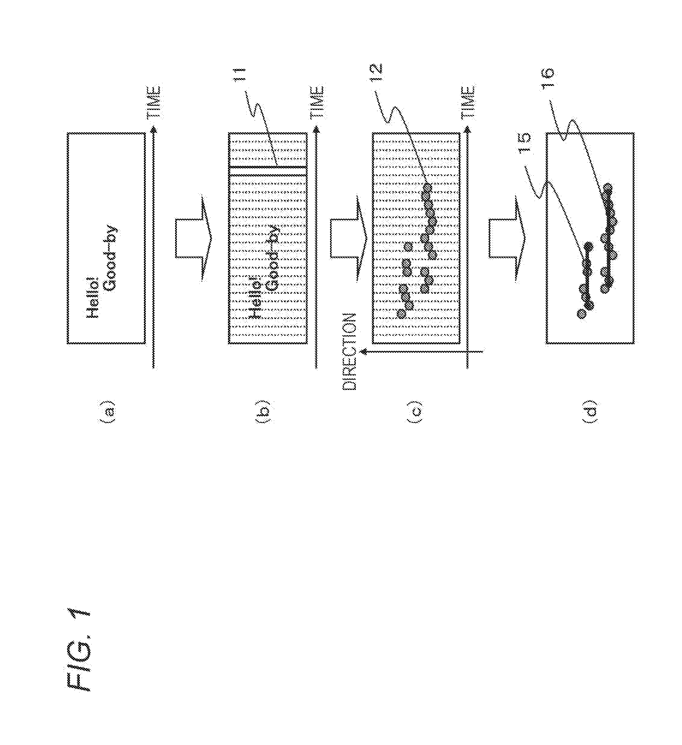
a sound signal processing and sound signal technology, applied in the direction of speech analysis, speech recognition, direction finders, etc., can solve the problems of system wrong operation, speech recognition accuracy, wrong recognition, etc., and achieve the effect of high degree of accuracy and high degree of accuracy

Active Publication Date: 2017-02-16
SONY CORP
View PDF10 Cites 16 Cited by
  • Summary
  • Abstract
  • Description
  • Claims
  • Application Information

AI Technical Summary

Benefits of technology

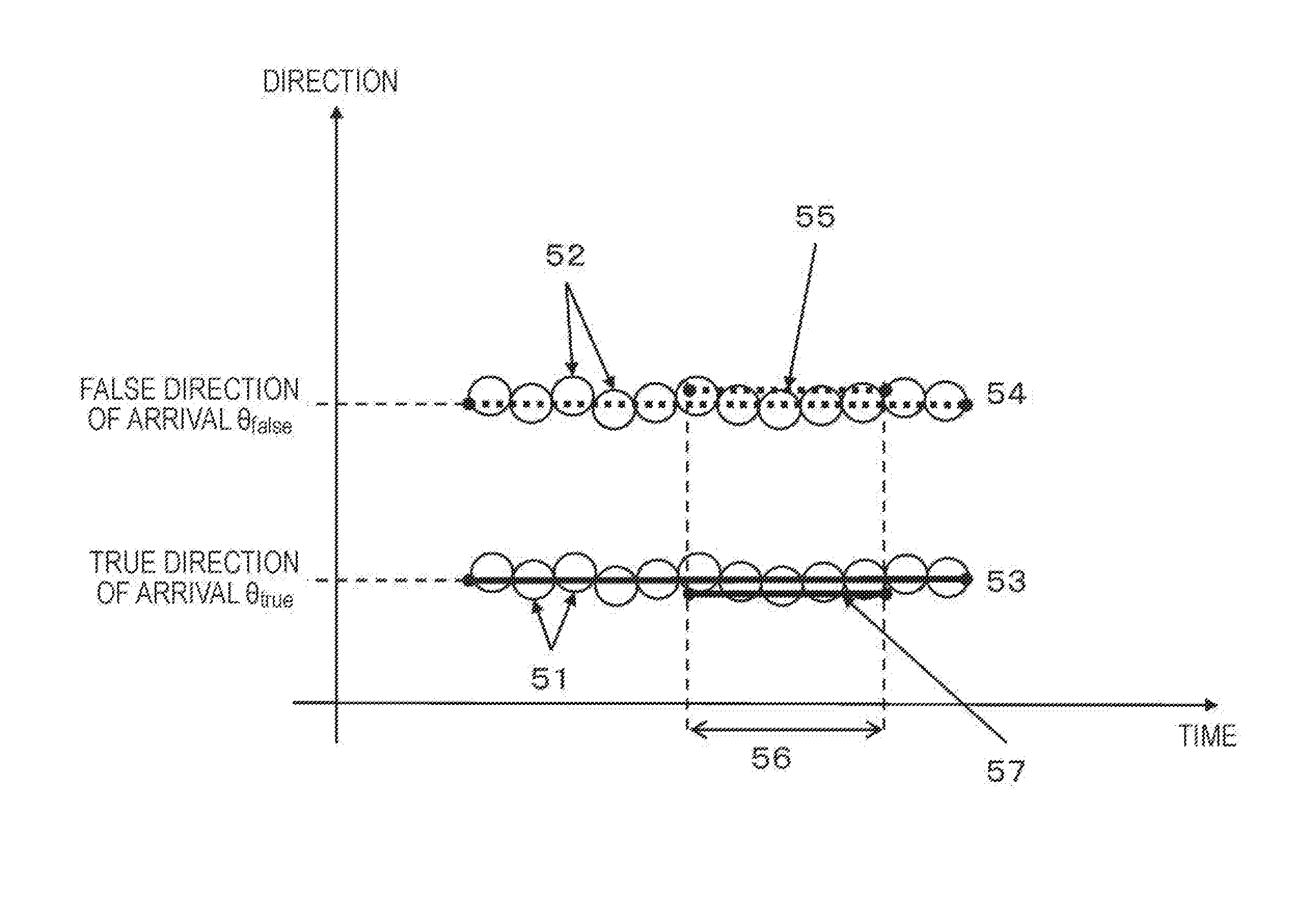
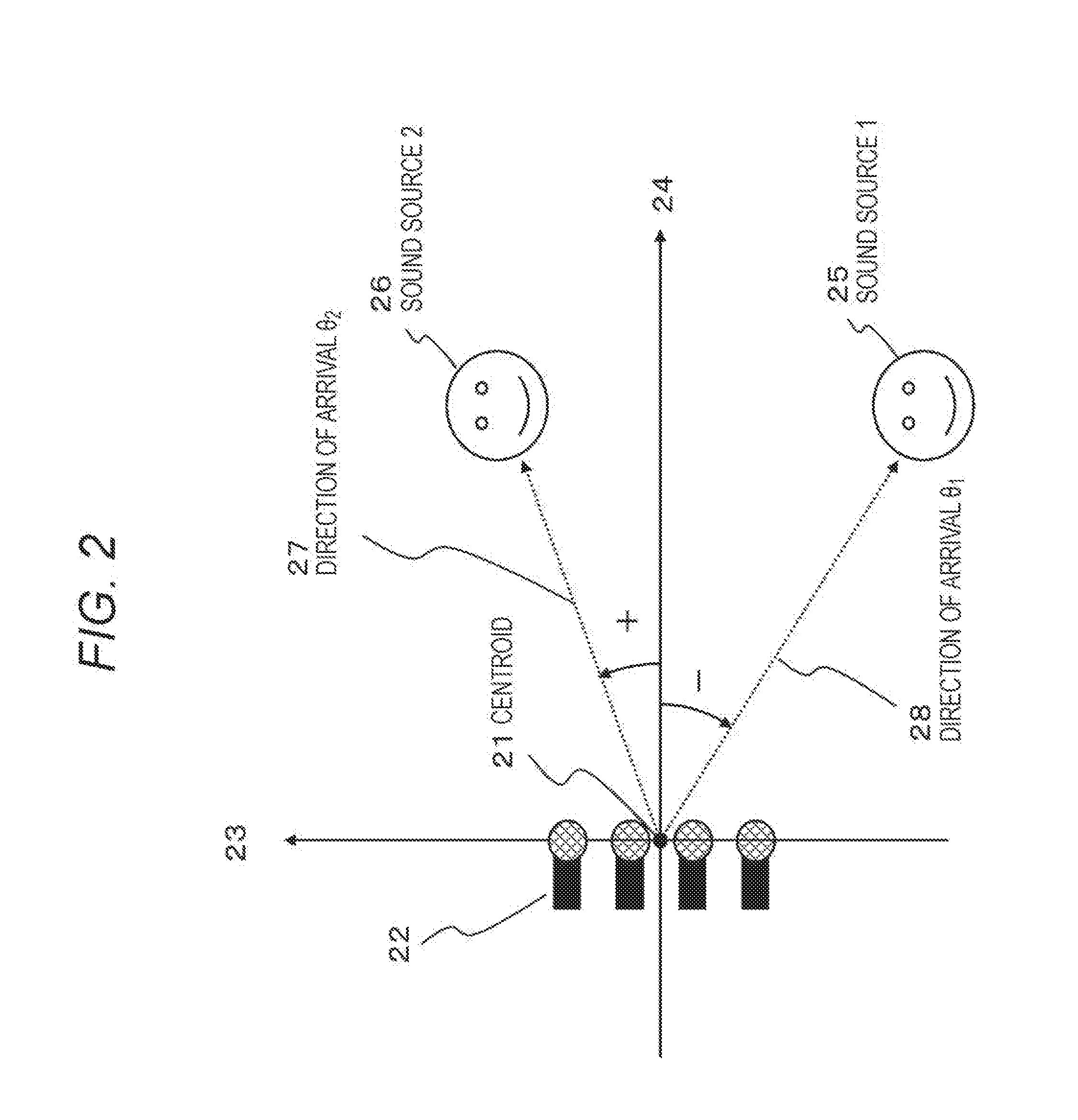
The present patent describes a device and method for accurately identifying speech segments from sound signals that have different sounds present. The device detects speech segments by connecting directional points that indicate the direction of arrival of the sound signal and generates patterns for classification. An average null beam pattern is also calculated for non-speech-like signals. A threshold is set to identify the local minimum point for each pattern, and the device finds the point that is within the set threshold to be the direction of arrival. This configuration allows for accurate identification of speech segments in complex sound signals.

Problems solved by technology

In many speech recognition devices, for example, processing such as matching is performed on segments cut out through segment detection, and therefore, the accuracy of speech recognition is greatly affected by the accuracy of the segment detection Specifically, if a segment during which a person has actually spoken differs from a segment detected through a segment detection process, the detection will cause wrong recognition.
In other cases, if a speech segment is wrongly detected even though any speech has not been emitted, a recognition process is performed on the sound in the segment, and the system wrongly operates in accordance with the wrong recognition result.

Method used


Image

  • Sound signal processing device, sound signal processing method, and program
  • Sound signal processing device, sound signal processing method, and program
  • Sound signal processing device, sound signal processing method, and program

Examples


Embodiment Construction

[0092]The following is a detailed description of a sound signal processing device, a sound signal processing method, and a program of the present disclosure, with reference to the drawings.

[0093]Before the configuration and the process according to the present disclosure are described, the symbols to be used in this specification are explained below.

[0094]The symbols to be used in this specification have the meanings described below.

[0095](1) “_” represents a subscript.

[0096](Example) φ_ω . . . ω is a subscript.

[0097]However, “_k” indicating a channel number will often appear, and therefore, “_” will be omitted.

[0098](Example) Y_k(t)→Yk(t).

[0099]In a case where there are two or more subscripts, the subscripts are put into { . . . }. (Example) θ_{i′}: i′ are subscripts.

[0100](2) “̂” represents a superscript.

[0101](Example 1) ŴH: Hermitian transpose (=complex transpose) of W.

[0102](Example 2) Yk(t)̂H: Hermitian transposed vector (conjugated complex number and transpose) of Yk(t).

[010...


PUM


Abstract

A device and a method for determining a speech segment with a high degree of accuracy from a sound signal in which different sounds coexist are provided. Directional points indicating the direction of arrival of the sound signal are connected in the temporal direction, and a speech segment is detected. In this configuration, pattern classification is performed in accordance with directional characteristics with respect to the direction of arrival, and a directionality pattern and a null beam pattern are generated from the classification results. Also, an average null beam pattern is also generated by calculating the average of the null beam patterns at a time when a non-speech-like signal is input. Further, a threshold that is set at a slightly lower value than the average null beam pattern is calculated as the threshold to be used in detecting the local minimum point corresponding to the direction of arrival from each null beam pattern, and a local minimum point equal to or lower than the threshold is determined to be the point corresponding to the direction of arrival.

Description

TECHNICAL FIELD[0001]The present disclosure relates to a sound signal processing device, a sound signal processing method, and a program. More particularly, the present disclosure relates to a sound signal processing device that performs a speech detection process accompanied by estimation of a direction of arrival, a sound signal processing method, and a program.BACKGROUND ART[0002]Speech detection (SD) is a process to be performed to cut out a segment, during which a person is speaking, from a sound signal that is continuously input. This process is also called voice activity detection (VAD). Hereinafter, speech detection will also be referred to as “segment detection”.[0003]Speech detection may be performed together with speech recognition, sound source extraction, and the like. In any case, a high degree of accuracy is required in segment detection.[0004]In many speech recognition devices, for example, processing such as matching is performed on segments cut out through segment ...

Claims


Application Information

Patent Timeline
Patent Type & Authority Applications(United States)
IPC IPC(8): G10L21/028G10L25/93G10L21/0388
CPCG10L21/028G10L2021/02166G10L25/93G10L21/0388G10L15/04G10L25/78G10L21/0308G01S3/8006G01S3/8083
Inventor HIROE, ATSUO
Owner SONY CORP
Learn More