
Direct-current power transmission protection device, converter and protection method

a protection device and converter technology, applied in the direction of electrical equipment construction details, emergency protection circuit arrangement, etc., can solve the problem of maximum probability of fault occurrence, equipment may suffer from loss, and the conventional direct-current power transmission system is rarely out of operation, so as to shorten the fault current attenuation time, reduce the risk of loss, and reduce the effect of short circuit curren

Inactive Publication Date: 2017-02-16
NR ELECTRIC CO LTD +1
View PDF7 Cites 22 Cited by
  • Summary
  • Abstract
  • Description
  • Claims
  • Application Information

AI Technical Summary

Benefits of technology

The present invention provides a protection device, converter, and protection method for flexible direct-current power transmission that can effectively resolve the disadvantages of difficult short circuit current attenuation and oscillation. The protection device can quickly and effectively suppress direct-current short circuit current and damp current oscillation, and can better protect equipment safety, shorten fault current attenuation time, and decrease economic loss and system destabilization risk caused by shutdown. The protection device is structurally simple and low in cost, and has good implementability and economic efficiency.

Problems solved by technology

Once a fault occurs, the equipment may suffer from loss due to over-voltage or over-current surges.
Direct-current transmission lines may probably reach thousands of kilometers and are exposed to the complex natural environment, and therefore have a maximum probability of fault occurrence.
Fortunately, such a permanent fault only accounts for a very small proportion among direct-current transmission line faults, so the conventional direct-current power transmission system is rarely out of operation due to the short circuit of the direct-current transmission lines.
However, such a good protection method is not fully feasible in flexible direct-current power transmission.
The flexible direct-current power transmission system adopts IGBTs to compose a voltage source converter, direct-current voltage therefore cannot be reversed by means of the control of the converter, and therefore the method cannot suppress short circuit current either.
(1) Diode devices are connected in parallel in the flexible direct-current power transmission converter, providing a loop for direct-current short circuit current when the direct-current short circuit fault occurs, the attenuation of the short circuit current in the direct-current loop is difficult due to the existence of the diodes even if the alternating-current incoming breaker is switched on, as a result, on one hand, the equipment will be exposed to high-current surges for a longer time, on the other hand, the whole system recovery time will be prolonged greatly, and consequently, economic loss and system destabilization risk will be exacerbated.
(2) When short circuit occurs, the equipment of the flexible direct-current power transmission system, such as inductors and capacitors, may oscillate short circuit current, which further increases the destructive power of the short circuit current on equipment and peripheral systems.
However, because the technical maturity of the equipment is not enough for engineering application, the equipment still cannot be adopted for a long time.
Even if the application technique becomes mature in the future, the equipment thereof is complex and has a high manufacturing cost, a great workload of operation and maintenance, and a poor economic efficiency.

Method used


Image

  • Direct-current power transmission protection device, converter and protection method
  • Direct-current power transmission protection device, converter and protection method
  • Direct-current power transmission protection device, converter and protection method

Examples


Embodiment Construction

[0034]In reference to the drawings, the technical solution of the present invention is described in detail below.

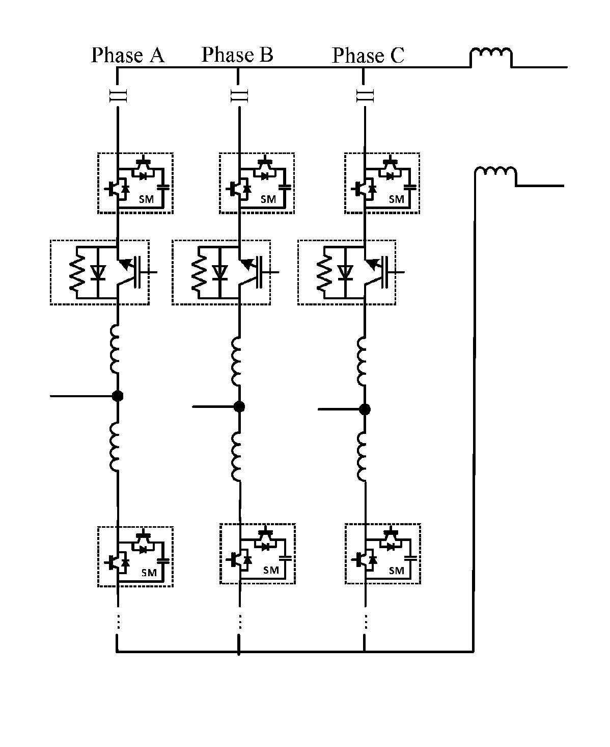
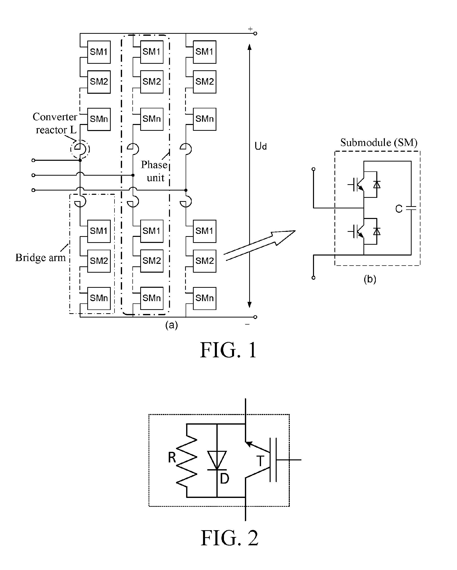
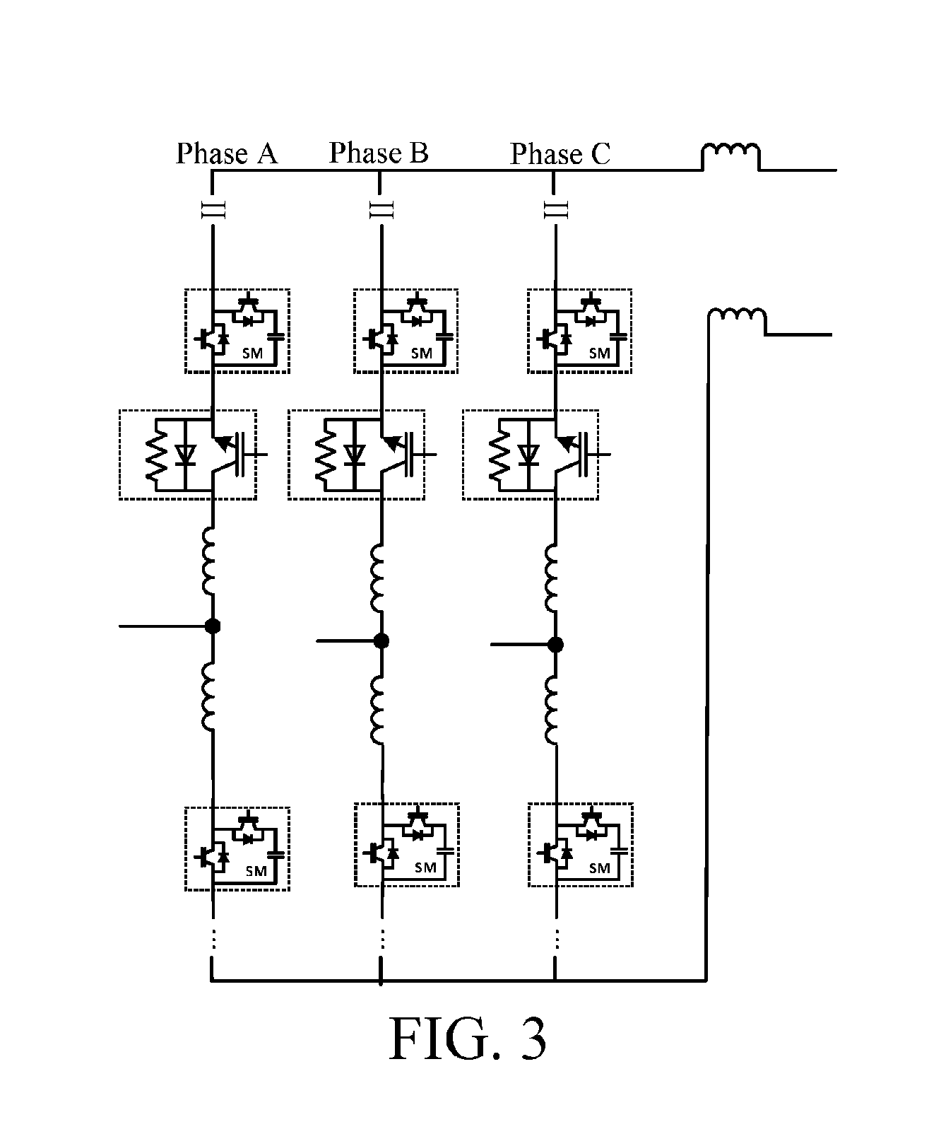
[0035]FIG. 1 shows the topological structure of a converter. The converter includes three phases, each phase comprises an upper bridge arm and a lower bridge arm, and the converter comprises six bridge arms in total. A reactor L and N submodules SM are connected in series to form each bridge arm, and the upper bridge arm and lower bridge arm of each phase are combined together to form a phase unit. A joint of the upper bridge arm and the lower bridge arm is a midpoint. Leading-out terminals of the three upper bridge arms are connected together to serve as a positive terminal of the converter; and the leading-out terminals of the three lower bridge arms are connected together to serve as a negative terminal of the converter.

[0036]The present invention provides a protection device, which comprises a resistor unit and a bidirectional circulation current switch unit, and the ...


PUM


Abstract

The present invention discloses a direct-current power transmission protection device, including a resistor unit and a bidirectional circulation current switch unit, and the resistor unit and the bidirectional circulation current switch unit being connected in parallel to form the protection device, where at least one resistor is cascaded to form the resistor unit, and at least one bidirectional circulation current switch is cascaded to form the bidirectional circulation current switch unit. In addition, the present invention also provides a converter including the protection device, and at least one protection device is connected in series in each phase unit. The present invention provides the protection device, the converter and a protection method for flexible direct-current power transmission, which can rapidly and effectively suppress direct-current short circuit current and damp current oscillation, and not only can better protect equipment safety, but also can greatly shorten fault current attenuation time, thus shortening direct-current shutdown time and further decreasing economic loss and system destabilization risk caused by shutdown to the max. Moreover, the protection device is structurally simple and low in cost, and has good implementability and economic efficiency.

Description

TECHNICAL FIELD[0001]The present invention relates to the field of direct-current power transmission, and in particular, to a protection device for a direct-current short circuit fault of flexible direct-current power transmission, a converter including the protection device and a protection method therefor.BACKGROUND ART[0002]The direct-current power transmission technique (HVDC, High-Voltage Direct Current) is a transmission technique for transmitting electrical energy in form of direct current through alternating current / direct current and direct current / alternating current conversions by means of high-power half-controlled power electronic devices (such as thyristors) or fully-controlled power electronic devices (such as insulated gate bipolar transistors (IGBT) and integrated gate commutated thyristors (IGCT)). The direct-current power transmission using the half-controlled power electronic devices (thyristors) is called a current source converter-based direct-current power tra...

Claims


Application Information

Patent Timeline
IPC IPC(8): H02H3/20H02M7/217H05K7/20H02H7/125
CPCH02H3/202H05K7/20927H02M7/2173H02H7/1252H02M1/32H02H7/10H02H7/1227H02H7/1257H02H7/127H02M7/4835Y02E60/60
Inventor CAO, DONGMINGXIE, YEYUANSHAO, ZHENXIALU, YULI, MINLU, HAIBINLI, HAIYING
Owner NR ELECTRIC CO LTD
Learn More