
Method, systems and apparatus for hdr to hdr inverse tone mapping

a technology of inverse tone mapping and hdr, applied in the field of image and video processing, can solve the problems of reducing experience, not providing sufficient control to be used within a color grading context, and digital and analog imaging technologies, so as to achieve high peak luminance

Inactive Publication Date: 2017-02-16
INTERDIGITAL VC HLDG INC
View PDF1 Cites 21 Cited by
  • Summary
  • Abstract
  • Description
  • Claims
  • Application Information

AI Technical Summary

Benefits of technology

This patent is about a method, device, or system that uses a technique called HDR to create high dynamic range (HDR) images. These images can be part of a video, and the technique involves using information from previous frames to achieve temporal stability. The technical effect of this patent is to improve the quality of HDR images and enhance their overall visual appearance.

Problems solved by technology

Yet traditional imaging technologies, both digital and analog, offer diminished experience because they cannot parallel the wide range of luminance and contrast that is visible to human eyes.
Although there are HDR displays, and although cameras capable of capturing an increased dynamic range are being developed, there is still very limited HDR content available.
Existing ITMO solutions are rarely created with video in mind and they do not provide sufficient controls to be used within a color grading context.
Existing ITMO solutions are problematic because they increase the range of luminance values by a very large amount.
The difference between light levels observed in the real world and the input (normally around 100 nits) is very significant, forcing the design of appropriate ITMOs to make trade-offs between visual quality and computational complexity.
This fits with the currently observed trend that display devices have a dynamic range that is increasingly less uniform.
With a large variety of displays with different capabilities deployed, content providers will not be able to provide separate grades for each different display.

Method used


Image

  • Method, systems and apparatus for hdr to hdr inverse tone mapping
  • Method, systems and apparatus for hdr to hdr inverse tone mapping
  • Method, systems and apparatus for hdr to hdr inverse tone mapping

Examples


Embodiment Construction

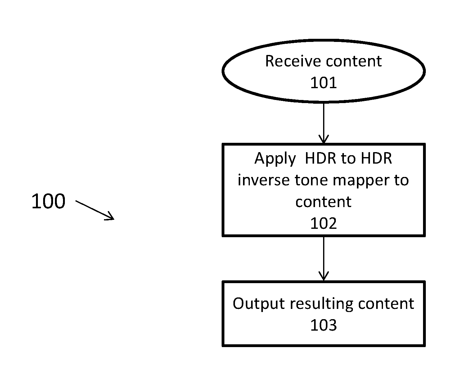
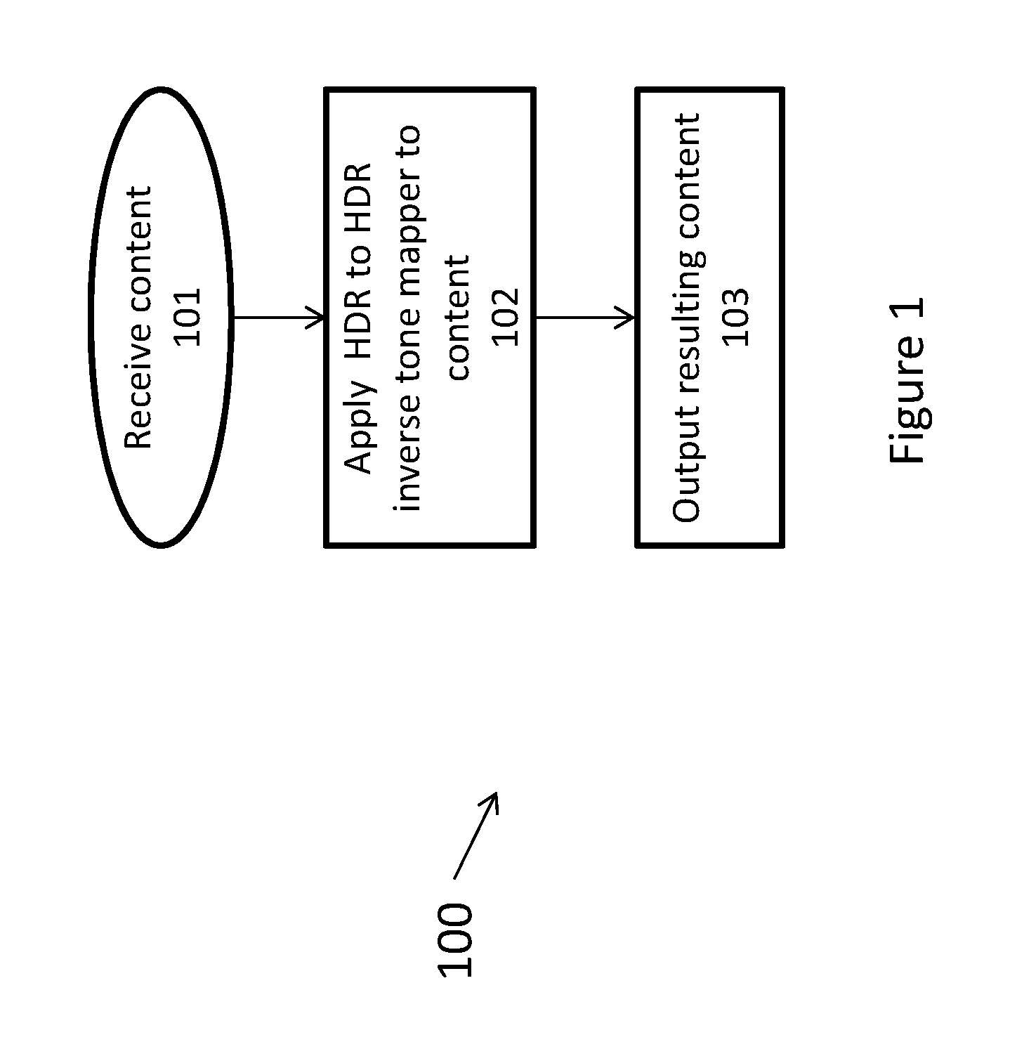
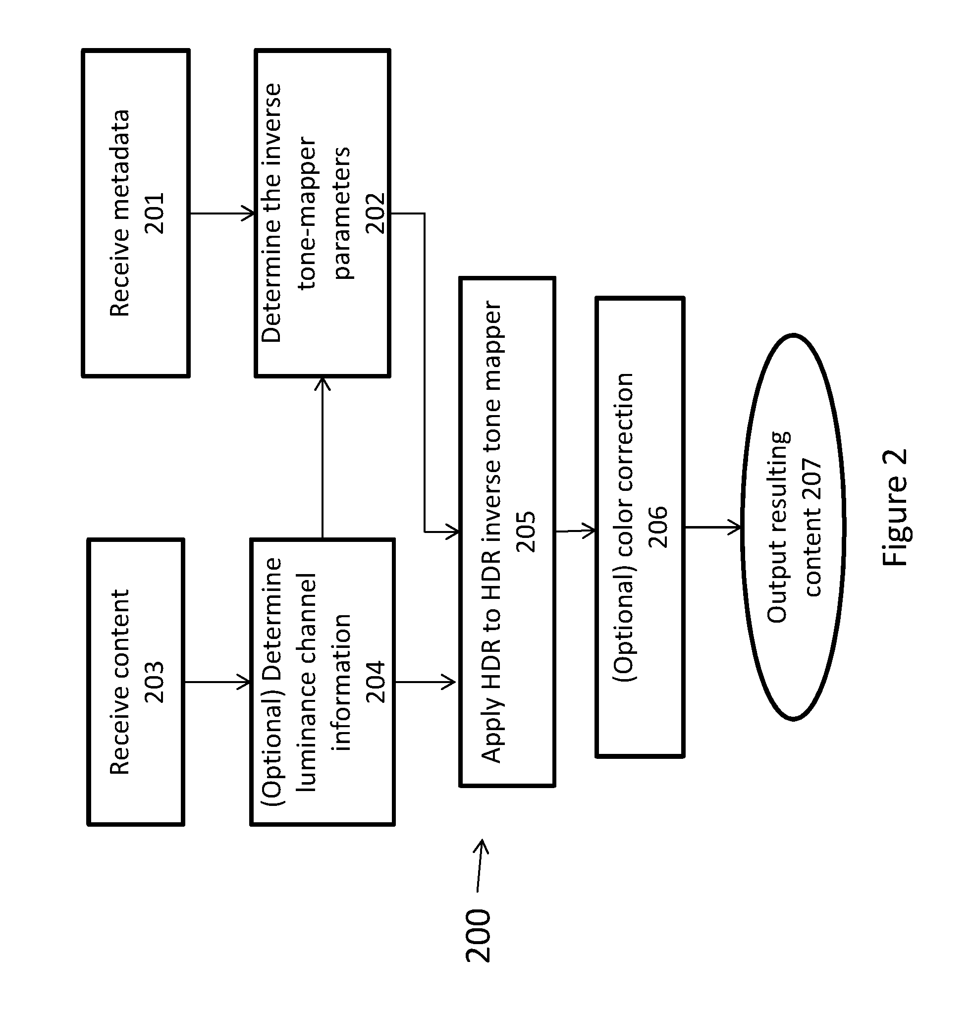
[0028]The present principles are directed to methods, apparatus and systems for HDR to HDR inverse tone mapping and / or an HDR to HDR inverse tone mapper.

[0029]An aspect of present principles may be implemented in hardware such as Field Programmable Gate Arrays (FPGAs) and Systems on Chip (SoCs), although it could be implemented without restriction in other types of hardware such as general purpose processing units and graphics processing units. The minimal processing capabilities of FPGAs and SoCs, combined with the increasing need for processing due to higher frame resolutions (such as UHD or 4K content) as well as higher frame rates, may limit the processing that can be implemented on such devices. The present principles address the problem of inverse tone reproduction in a manner consistent with such potential device limitations.

[0030]An aspect of present principles is directed to tone reproduction and inverse tone reproduction that may be used as part of an encoding / decoding sch...


PUM


Abstract

The present invention proposes to provide methods, apparatus and systems for inverse tone mapping of a high dynamic range image. The method may include the operations of obtaining a luminance component of the high dynamic range image. The method may further include determining an HDR to HDR inverse tone mapper operator. The method may further include determining a tone expanded image by applying the HDR to HDR inverse tone mapper to the luminance component of the high dynamic range image. The method may further include wherein the HDR to HDR inverse tone mapper curve comprises a linear part for dark and mid-tone levels, and an expanding non-linear part for highlights. The system or apparatus may be configured to perform the operations of the method.

Description

TECHNICAL FIELD[0001]The present disclosure relates to image and video processing. In particular, the present disclosure relates to conversion of image or video data utilizing a High Dynamic Range (“HDR”) inverse tone mapping operator.BACKGROUND[0002]Light in nature covers an enormous range of luminance levels, from starlight to bright sunlight. Yet traditional imaging technologies, both digital and analog, offer diminished experience because they cannot parallel the wide range of luminance and contrast that is visible to human eyes. In response, HDR technologies are being developed to allow for the display of an extended range of color, luminance and contrast. HDR technologies focus on capturing, processing and displaying content of a wider dynamic range. Although there are HDR displays, and although cameras capable of capturing an increased dynamic range are being developed, there is still very limited HDR content available.[0003]To prepare conventional content for HDR displays, r...

Claims


Application Information

Patent Timeline
Patent Type & Authority Applications(United States)
IPC IPC(8): H04N19/105H04N19/134H04N19/186H04N19/126
CPCH04N19/105H04N19/186H04N19/134H04N19/126H04N19/184H04N19/36H04N19/44H04N23/741H04N19/103H04N19/136H04N19/172G06T5/50G06T2207/20208G06T5/90
Inventor SEIFI, MOZHDEHREINHARD, ERIK
Owner INTERDIGITAL VC HLDG INC
Learn More