Operation methods of communication node in network supporting licensed and unlicensed bands
a communication node and network technology, applied in the direction of transmission path sub-channel allocation, wireless communication, transmission path division, etc., can solve the problems of limited resources of licensed bands and transmission of unnecessary information, and achieve the effect of improving the performance of the communication network
- Summary
- Abstract
- Description
- Claims
- Application Information
AI Technical Summary
Benefits of technology
Problems solved by technology
Method used
Image
Examples
first embodiment
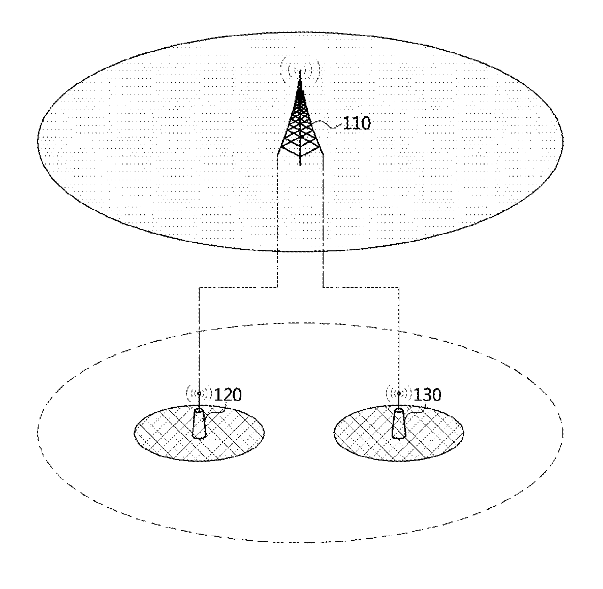
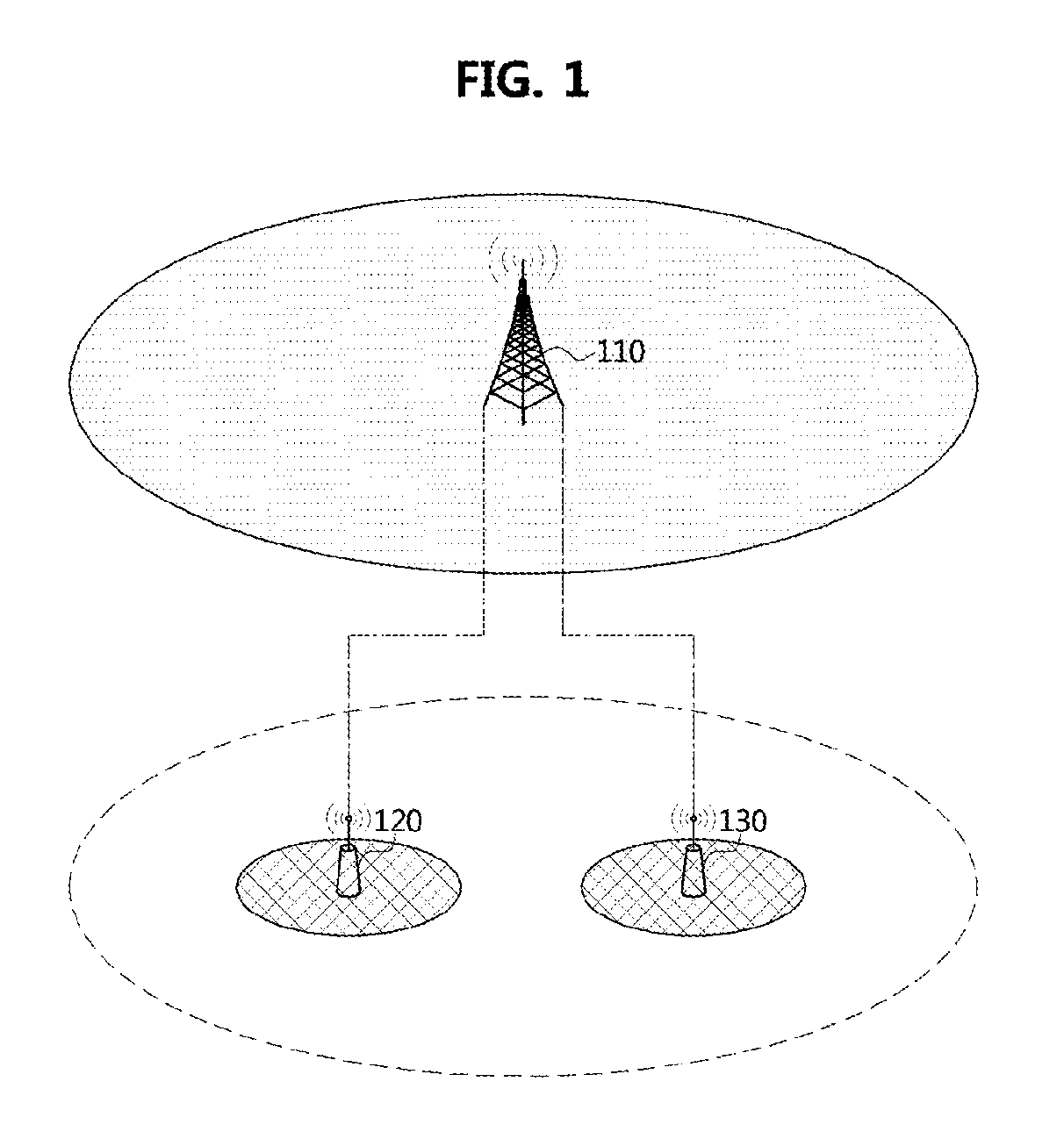
[0061]FIG. 1 is a conceptual diagram illustrating a wireless communication network. p Referring to FIG. 1, a first base station 110 may support cellular communications (e.g., Long Term Evolution (LTE), LTE-Advanced (LTE-A), Licensed Assisted Access (LAA), etc. standardized in a 3rd Generation Partnership Project (3GPP)). The first base station 110 may support technologies such as a Multiple Input Multiple Output (MIMO) (e.g., Single-User (SU)-MIMO, Multi-User (MU)-MIMO, massive MIMO, etc.), a Coordinated multi-point transmission / reception (CoMP), a Carrier Aggregation (CA), etc. The first base station 110 may operate in a licensed band (F1), and form a macro cell. The first base station 100 may be connected to other base stations (e.g., a second base station 120, a third base station 130, etc.) through ideal backhaul links or non-ideal backhaul links.
[0062]The second base station 120 may be located in coverage of the first base station 110. Also, the second base station 120 may oper...
second embodiment
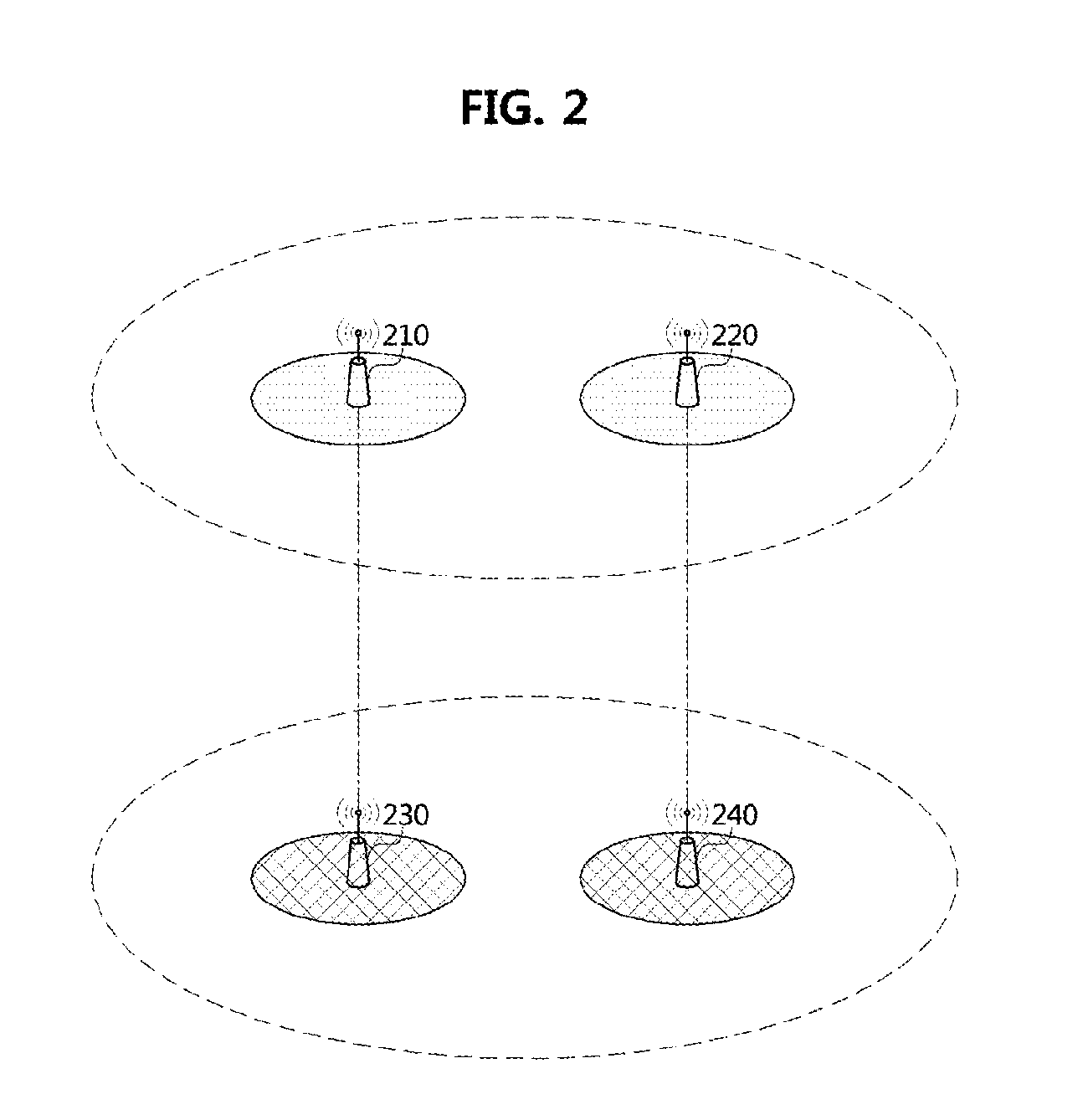
[0063]FIG. 2 is a conceptual diagram illustrating a wireless communication network.
[0064]Referring to FIG. 2, each of a first base station 210 and a second base station 220 may support cellular communications (e.g., LTE, LTE-A, LAA, etc.). Each of the first base station 210 and the second base station 220 may support MIMO (e.g., SU-MIMO, MU-MIMO, massive MIMO, etc.), CoMP, CA, etc. Also, each of the base stations 210 and 220 may operate in the licensed band (F1), and form each small cell. Each of the base stations 210 and 220 may be located in coverage of a base station forming a macro cell. The first base station 210 may be connected with a third base station 230 through an ideal backhaul link or a non-ideal backhaul link. Also, the second base station 220 may be connected with a fourth base station 240 through an ideal backhaul link or a non-ideal backhaul link.
[0065]The third base station 230 may be located in coverage of the first base station 210. The third base station 230 may...
third embodiment
[0066]FIG. 3 is a conceptual diagram illustrating a wireless communication network.
[0067]Referring to FIG. 3, each of a first base station 310, a second base station 320, and a third base station 330 may support cellular communications (e.g., LTE, LTE-A, LAA, etc.). Each of the first base station 310, the second base station 320, and the third base station 330 may support MIMO (e.g., SU-MIMO, MU-MIMO, massive MIMO, etc.), CoMP, CA, etc. The first base station 310 may operate in the licensed band (F1), and form a macro cell. The first base station 310 may be connected to other base stations (e.g., the second base station 320, the third base station 330, etc.) through ideal backhaul links or non-ideal backhaul links. The second base station 320 may be located in coverage of the first base station 310. The second base station 320 may operate in the licensed band (F1), and form a small cell. The third base station 330 may be located in coverage of the first base station 310. The third b...
PUM
 Abstract
Description
Claims
Application Information
 - R&D
- Intellectual Property
- Life Sciences
- Materials
- Tech Scout
- Unparalleled Data Quality
- Higher Quality Content
- 60% Fewer Hallucinations
Browse by: Latest US Patents, China's latest patents, Technical Efficacy Thesaurus, Application Domain, Technology Topic, Popular Technical Reports.
© 2025 PatSnap. All rights reserved.Legal|Privacy policy|Modern Slavery Act Transparency Statement|Sitemap|About US| Contact US: help@patsnap.com


