Liquid ejecting apparatus
- Summary
- Abstract
- Description
- Claims
- Application Information
AI Technical Summary
Benefits of technology
Problems solved by technology
Method used
Image

Examples
Embodiment Construction
[0024]Hereinafter, embodiments for executing the invention will be described with reference to accompanying drawings. The embodiments which will be described below are variously limited as specific examples of the invention, which are preferable; however, the scope of the invention is not limited to these embodiments when there is no description for limiting the invention, particularly, in the following descriptions. Hereinafter, an ink jet printer (hereinafter, referred to as printer) as a type of a liquid ejecting apparatus on which an ink jet recording head (hereinafter, referred to as recording head) as a type of a liquid ejecting head is mounted will be described as an example.
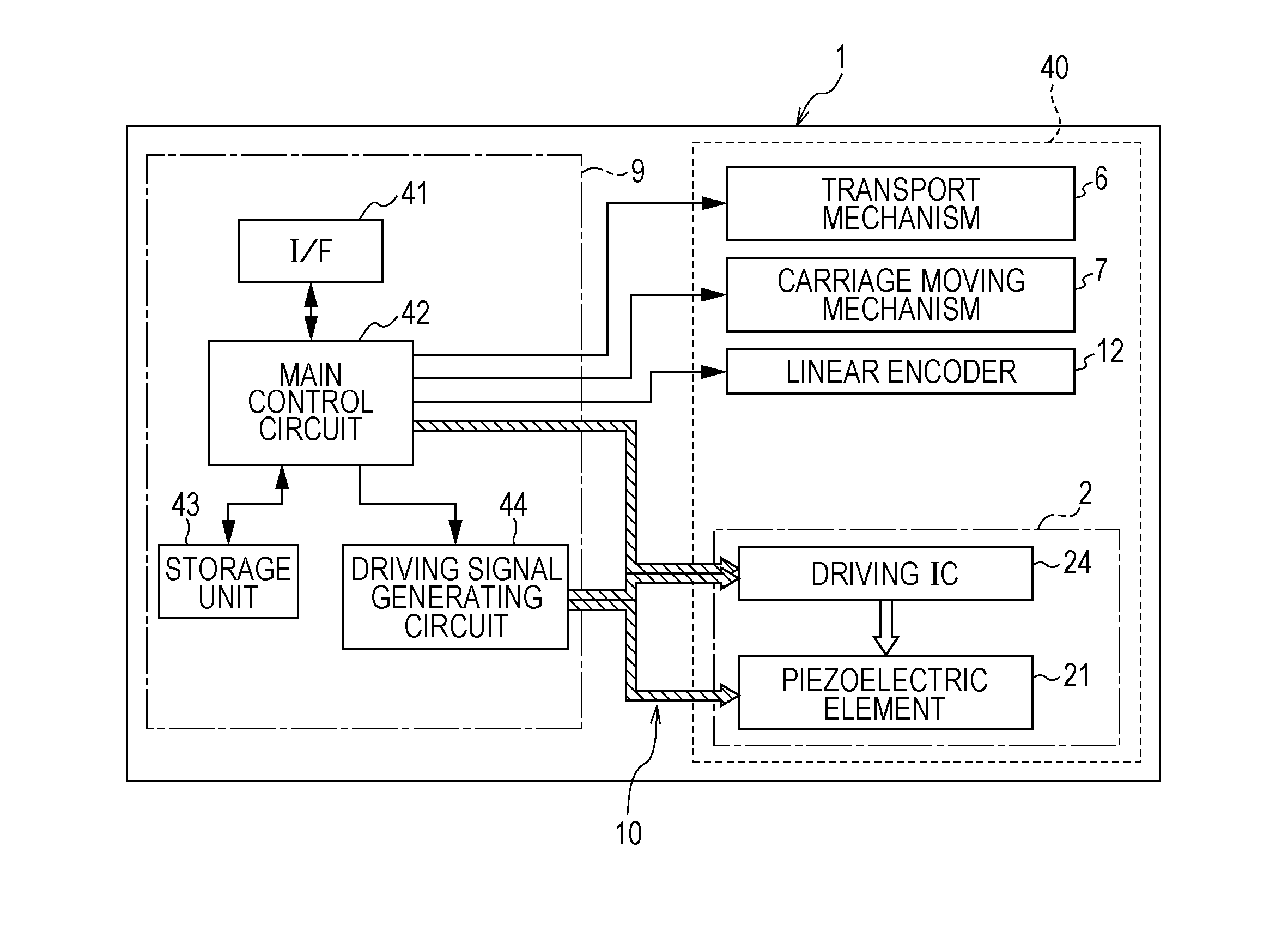
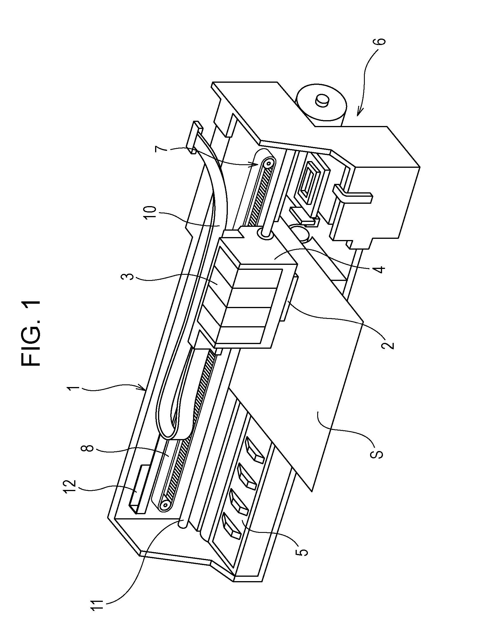
[0025]A printer 1 is provided with a carriage 4 on which a recording head 2 which is a type of a liquid ejecting head is mounted, and to which an ink cartridge 3 (a type of liquid storage member) is detachably attached, a platen 5 which is provided below the recording head 2, a carriage moving mechanism 7...
PUM
 Abstract
Description
Claims
Application Information