Hybrid crucible for crystallizing materials
Active Publication Date: 2017-03-02
ALD VACUUM TECH
View PDF1 Cites 0 Cited by
- Summary
- Abstract
- Description
- Claims
- Application Information
AI Technical Summary
Benefits of technology
[0046]In a preferred embodiment of the method the protective frame is positioned in the frame prior to the filling of the raw material and/or the seed material, so that the protective frame is preferably set onto the bottom plate, too. Alternatively, the protective frame can also be set onto the bottom plate prior to arranging the frame. The protective frame then remains on the bottom plate during the filling of the raw material and/or the seed material, so that the inner wall of the frame is protected from damage by sharp edges of the raw material. This is particularly of great advantage for sharp-edged silicon as a raw material.
[0047]The protective frame may preferably be removed from the area within the frame after the filling of the raw material and/or the seed material and in particular prior to the heat input or the melting process. The protective frame then only serves to protect the frame during the filling of the material. Thus, the lifetime of the frame is prolonged and the risk of con
Problems solved by technology
In one embodiment, however, ev
Method used
View moreImage
Smart ImageViewing Examples
Examples
Example
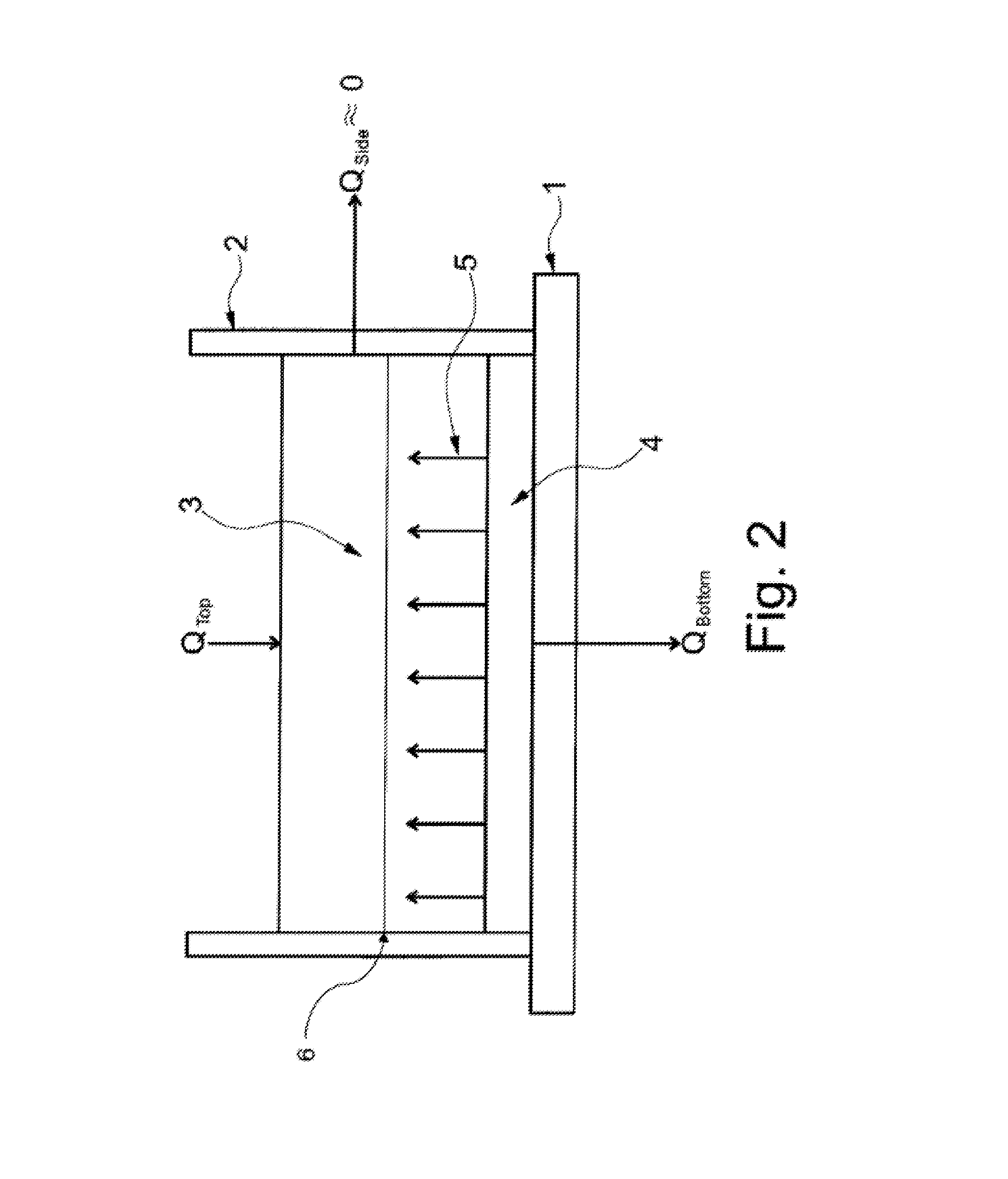
[0053]Due to the fact that the frame exhibits an insulating effect, the energy discharge at the sides is very low. Consequently, a temperature gradient is achieved only between the crystallization front and the bottom plate. The crystal growth thus only occurs from the bottom up.
LIST OF REFERENCE SYMBOLS
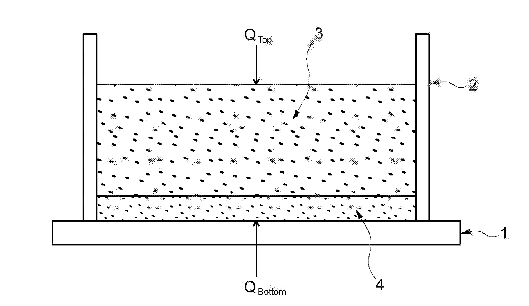
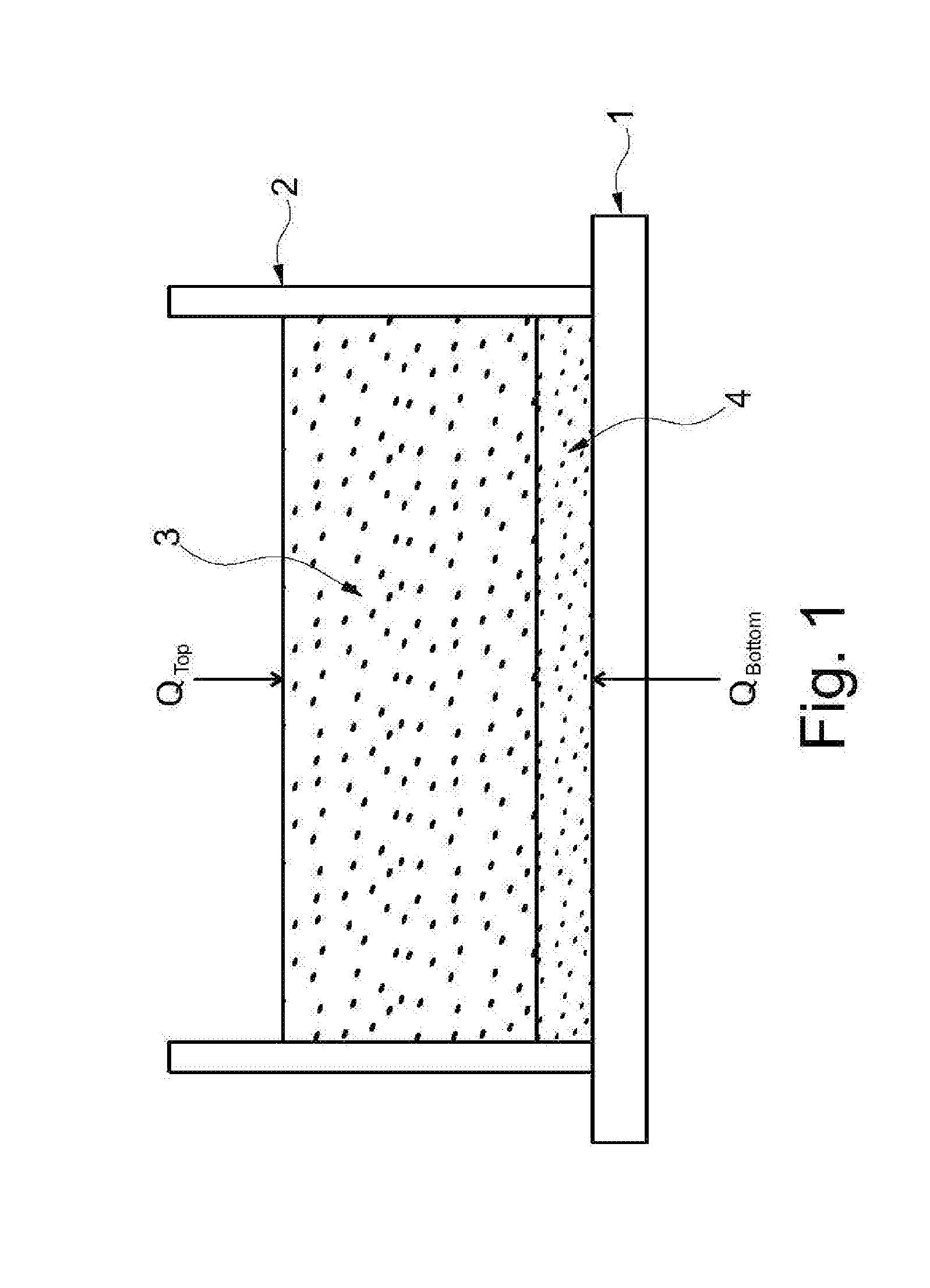
[0054]1 Bottom plate[0055]2 Frame[0056]3 Melt[0057]4 Solid bottom layer[0058]5 Direction of crystal growth[0059]6 Crystallization front
Login to View More PUM
 Abstract
A hybrid crucible comprising a frame and a bottom plate. The crucible is characterized by the selection of material of these two components, which have been optimized in terms of thermal conductivity. The crucible is adapted to produce crystalline materials. Moreover, a method for producing crystalline material is disclosed.
Description
FIELD OF THE INVENTION[0001]The present invention relates to a hybrid crucible for melting and crystallizing certain materials, in particular silicon. The invention also relates to a method for melting and crystallizing the materials in question.BACKGROUND OF THE INVENTION[0002]In the prior art primarily crucibles of silicon dioxide (quartz ceramics) are used for these purposes. In the crucibles of the prior art, the material to be melted is completely melted. To prevent leakage of the melt, these crucibles are constructed monolithically, i.e. frame and bottom plate are firmly joined together. In other words, crucibles of the prior art are typically made of silicon dioxide, whereby the thermal conductivity toward the bottom and towards the sides is equal. The crucibles used in the prior art require a massive increase in the temperature gradient toward the main heat flow during the solidification process. This massive increase of the temperature gradient reduces the degrees of freedo...
Claims
Login to View More Application Information
Patent Timeline
 IPC IPC(8): C30B11/00C30B29/06C30B11/14
CPCC30B11/002C30B29/06C30B11/14C30B11/003C30B35/002
Inventor FRANZ, HENRIKMORCHE, CHRISTOPHZIMMERMANN, ANDREASWENGERTER, ARMINMULLER, KAIHOHMANN, MICHAEL
Owner ALD VACUUM TECH
Features
- R&D
- Intellectual Property
- Life Sciences
- Materials
- Tech Scout
- Unparalleled Data Quality
- Higher Quality Content
- 60% Fewer Hallucinations
Learn More Browse by: Latest US Patents, China's latest patents, Technical Efficacy Thesaurus, Application Domain, Technology Topic, Popular Technical Reports.
© 2025 PatSnap. All rights reserved.Legal|Privacy policy|Modern Slavery Act Transparency Statement|Sitemap|About US| Contact US: help@patsnap.com


