
Battery Backup Capacity Method and System

Inactive Publication Date: 2017-03-02
FLUENCE ENERGY LLC
View PDF164 Cites 5 Cited by
  • Summary
  • Abstract
  • Description
  • Claims
  • Application Information

AI Technical Summary

Benefits of technology

This patent text describes how to determine the right amount of battery backup and the type of battery needed to meet minimum energy storage requirements. By using non-rechargeable batteries, the system can economically and efficiently provide the necessary energy storage capacity. This solution helps meet regulations while avoiding the waste of expensive rechargeable batteries or industrial-grade batteries.

Problems solved by technology

In addition, periods of peak load can also occur at different times during the day.
Such periods of high demand may exceed the capability of a utility's primary power generation source to respond.
Further, if other measures are not taken, the primary power generation source might need to have excess capacity to meet peak demand, with the excess capacity sitting idle and unused for all but the peak demand.
However, the real-world peak demand on an electric utility provider may never exceed the need to provide more than four hours' worth of backup energy capacity.
In this situation, a proportion of the battery system's resources are wasted in providing two hours' worth of available backup energy capacity, which will possibly never be used.
Backup battery storage systems often comprise expensive industrial grade, rechargeable cell batteries (known in the industry as “secondary batteries”) of uniform or similar types, specifically designed for backup energy services.
In such a situation, backup energy storage systems do not implement the most efficient utilization of resources.
Therefore, a problem exists when expensive backup energy storage system resources are wasted by providing available backup capacity that is required by regulating standards, but is not usually necessary to satisfy real-word demand placed on the power grid.

Method used


Image

  • Battery Backup Capacity Method and System
  • Battery Backup Capacity Method and System
  • Battery Backup Capacity Method and System

Examples


Embodiment Construction

[0025]This description provides exemplary embodiments only, and is not intended to limit the scope, applicability or configuration of the battery backup capacity methods and systems. Rather, the ensuing description of the embodiments will provide those skilled in the art with an enabling description for implementing various embodiments of the battery backup capacity methods and systems. Various changes may be made in the function and arrangement of elements without departing from the spirit and scope of the system and method as set forth in the appended claims. Thus, various embodiments may omit, substitute, or add various procedures or components as appropriate. For instance, it should be appreciated that in alternative embodiments, the methods may be performed in an order different than that described, and that various steps may be added, omitted or combined. Also, features described with respect to certain embodiments may be combined in various other embodiments. Different aspect...


PUM


Abstract

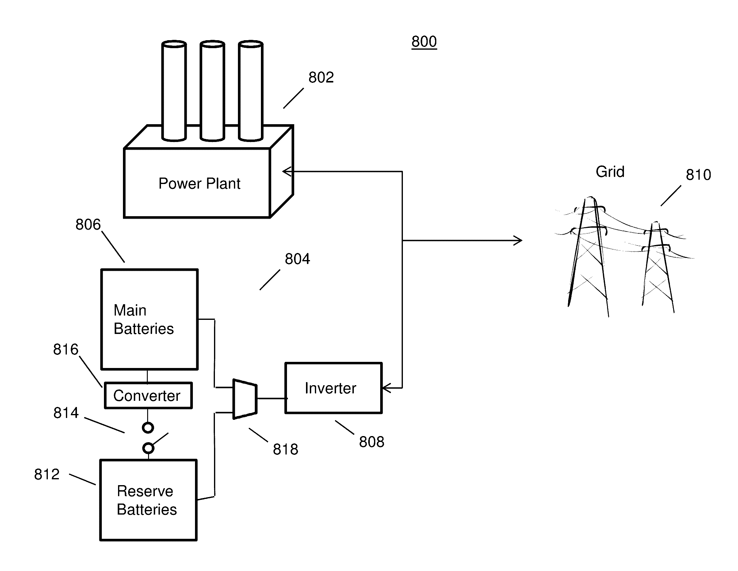
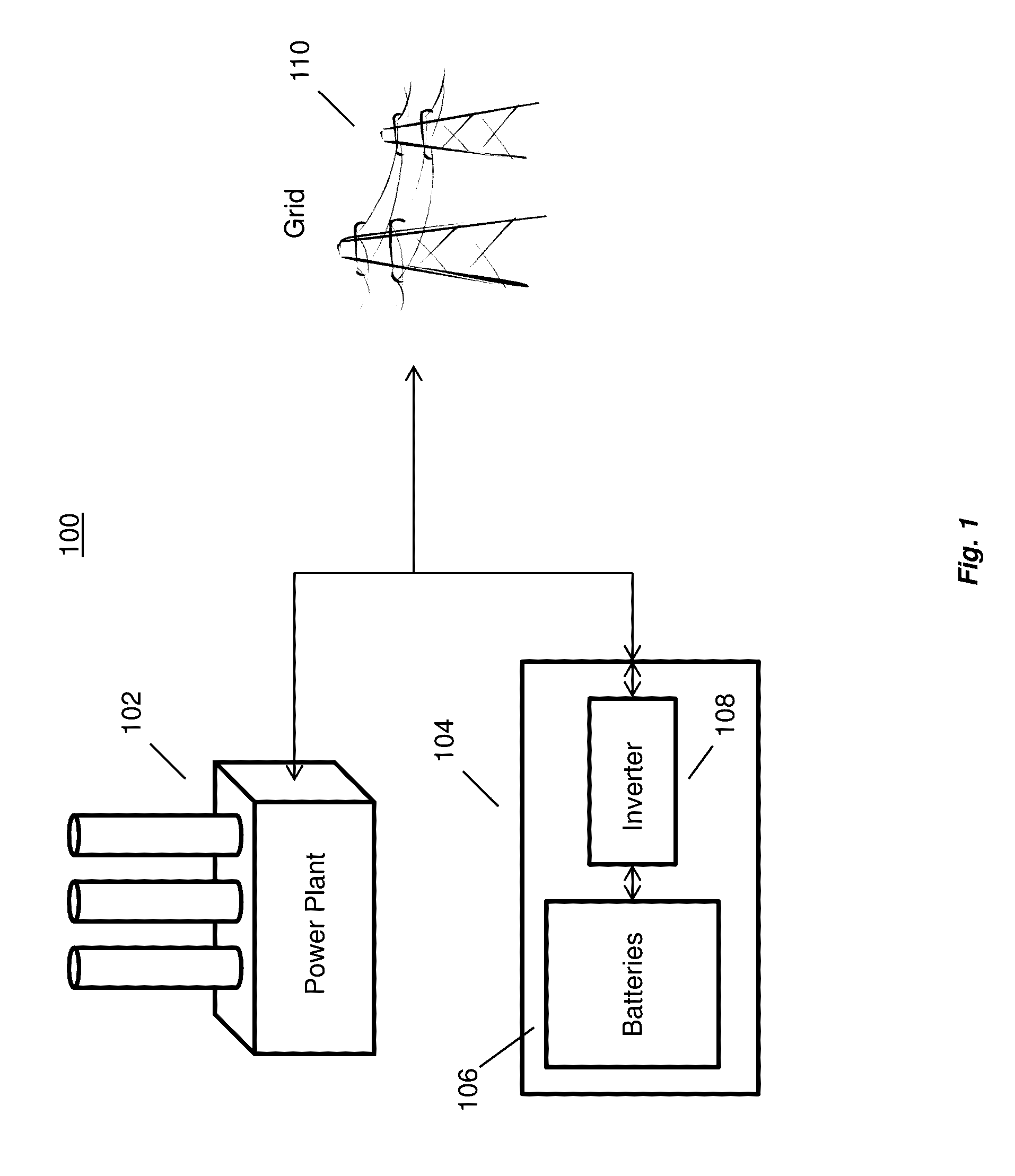
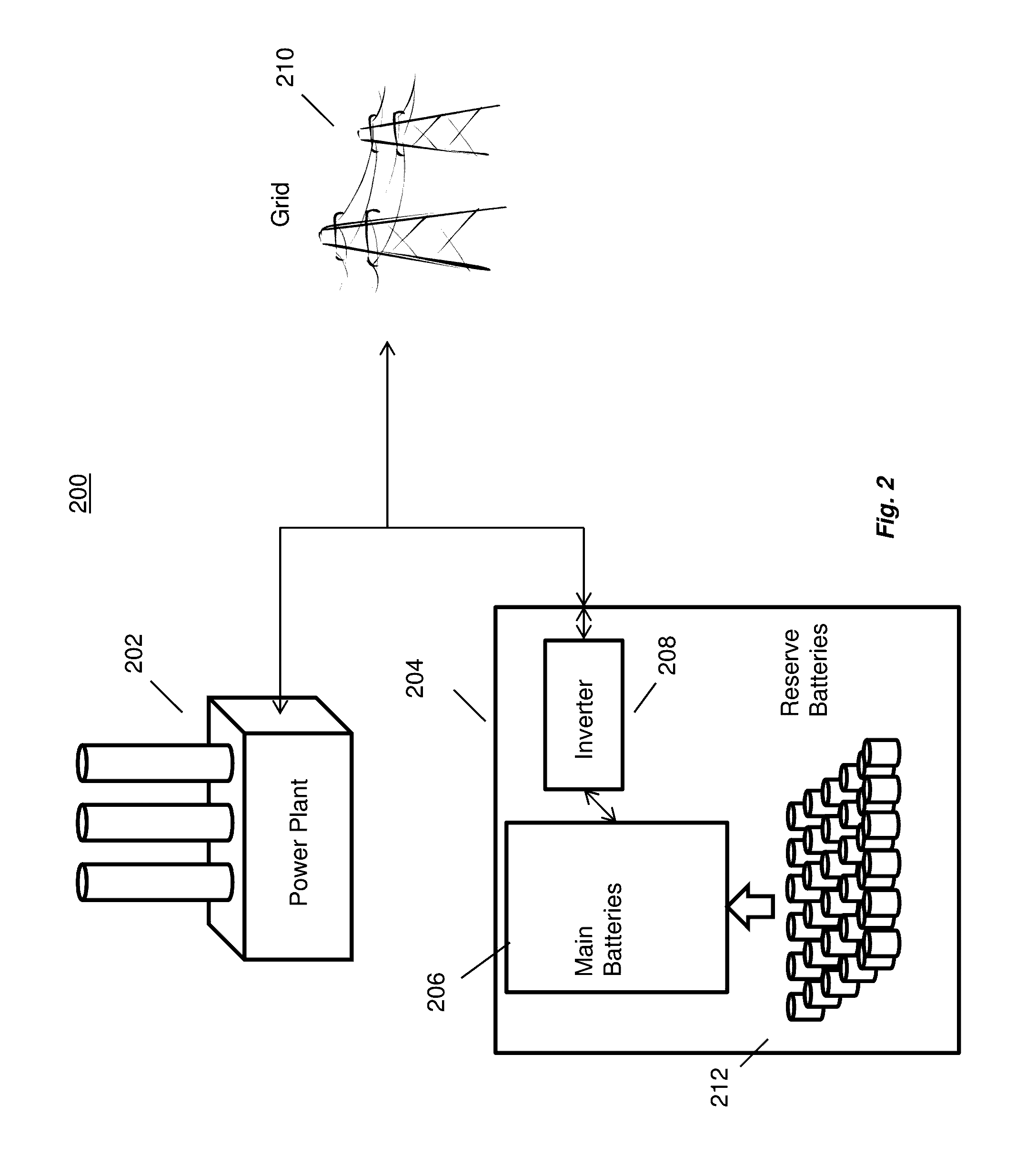
Approaches for providing backup energy services for a power grid are disclosed. In embodiments, methods and systems for obtaining a first group of reserve backup energy batteries of a first type, which have a different cost structure than a second group of main batteries of a second type. The first group of reserve batteries are combined with the second group of main batteries of the second type to increase a total amount of available energy that is stored and converting DC power from the first group of batteries and the second group of batteries to AC power to be used for power distribution to the grid.

Description

FIELD OF THE INVENTION[0001]The present disclosure is directed to methods and systems for providing backup energy services for a power grid and, more particularly, backup energy services for a hybrid electric generating power plant that uses batteries in an energy storage system or a standalone energy storage system for additional storage capability.BACKGROUND OF THE INVENTION[0002]Typically, a utility obtains electric power from one or more primary power generation sources, such as gas-fired, coal-fired, nuclear and / or hydroelectric power plants, for delivery to customers via a distribution grid. The power supplied by these sources and the demand placed on them can vary moment-to-moment. Generally, the sources can be regulated to meet the demands of customers while at the same time conforming to the standards for such power, such as nominal voltage and frequency levels.[0003]To supplement the power supplied by these primary power generation sources, it is becoming more common to co...

Claims


Application Information

Patent Timeline
IPC IPC(8): H02J7/02H02J7/04H02J7/00
CPCH02J7/022H02J7/0042H02J7/04H02J7/0021H02J3/32H02J7/00047Y04S20/20Y02B70/30Y02P70/50H02J7/0047H02J2207/20H02J7/00H02J9/04
Inventor SHELTON, JOHN C.PERUSE, BRIANGALURA, BRETTJEFFERSON, ISAIAHJACOBSON, JR., WELLS CASEGEINZER, JAY
Owner FLUENCE ENERGY LLC
Learn More