Steering reaction force control apparatus for vehicle

a technology of reaction force control and steering spring, which is applied in the direction of electric steering, vehicle components, power driven steering, etc., can solve the problems that the steering spring force based on the target steering spring force interferes with the steering operation of the driver

Active Publication Date: 2017-03-09
TOYOTA JIDOSHA KK
View PDF0 Cites 9 Cited by
  • Summary
  • Abstract
  • Description
  • Claims
  • Application Information

AI Technical Summary

Benefits of technology

[0010]It is a primary object of exemplary aspects of the present disclosure to improve, in control for a steering reaction force in a vehicle including a driving support device, a property of steered wheels to follow a target steered angle without a decrease in an operability of override steering in an automatic steering mode.
[0014]With the above-mentioned configuration, when the magnitude of the steering indication value for calculating the target steering spring force is less than the reference value, the target steering spring force is calculated so that the magnitude of the target steering spring force becomes larger in the case in which the driving support device is operating compared with the case in which the driving support device is not operating. The steering spring force that is based on the target steering spring force when the driving support device is operating acts as a force of causing the actual steered angle of the steered wheels to approach the target steered angle. Thus, the property of the steered wheels to follow the target steered angle when the driving support device is operating can be improved.
[0015]When the magnitude of the steering indication value for calculating the target steering spring force is equal to or more than the reference value, the target steering spring force does not need to be calculated so that the magnitude of the target steering spring force becomes larger in the case in which the driving support device is operating compared with the case in which the driving support device is not operating. Thus, the force for causing the steered angle of the steered wheels to approach the target steered angle does not become large, and thus, the operability of the override steering in the automatic steering mode does not deteriorate.
[0019]With the above-mentioned configuration, when the magnitude of the steering indication value for calculating the target steering spring force is more than the reference value, the target steering spring force is calculated so that the magnitude of the target steering spring force becomes larger in the case in which the driving support device is operating compared with the case in which the driving support device is not operating. Thus, the action of causing the actual steered angle of the steered wheels to approach the target steered angle is reduced. Thus, when the driver carries out the override steering at an operation amount that is large in magnitude toward the direction of causing the actual steered angle of the steered wheels to depart from the target steered angle, such a fear that the steering spring force that is based on the target steering spring force interferes with the steering operation of the driver can be reduced, thereby improving a steering property of the override steering.
[0021]In the above-mentioned aspect, the difference in the target steering spring force gradually increases from 0 as the magnitude of the difference between the magnitude of the steering indication value for calculating the target steering spring force and the reference value increases from the reference value in the range equal to or less than the predetermined value. Thus, when the magnitude of the steering indication value for calculating the target steering spring force increases / decreases beyond the reference value, the magnitude of the target steering spring force can be prevented from drastically changing.

Problems solved by technology

Thus, when the driver carries out a steering operation for the override steering toward such a direction that the actual steered angle of the steered wheels departs from the target steered angle, the steering spring force that is based on the target steering spring force interferes with the steering operation of the driver.

Method used


Image

  • Steering reaction force control apparatus for vehicle
  • Steering reaction force control apparatus for vehicle
  • Steering reaction force control apparatus for vehicle

Examples


Embodiment Construction

[0033]Now, referring to the accompanying drawings, preferred embodiments of the present disclosure are described in detail.

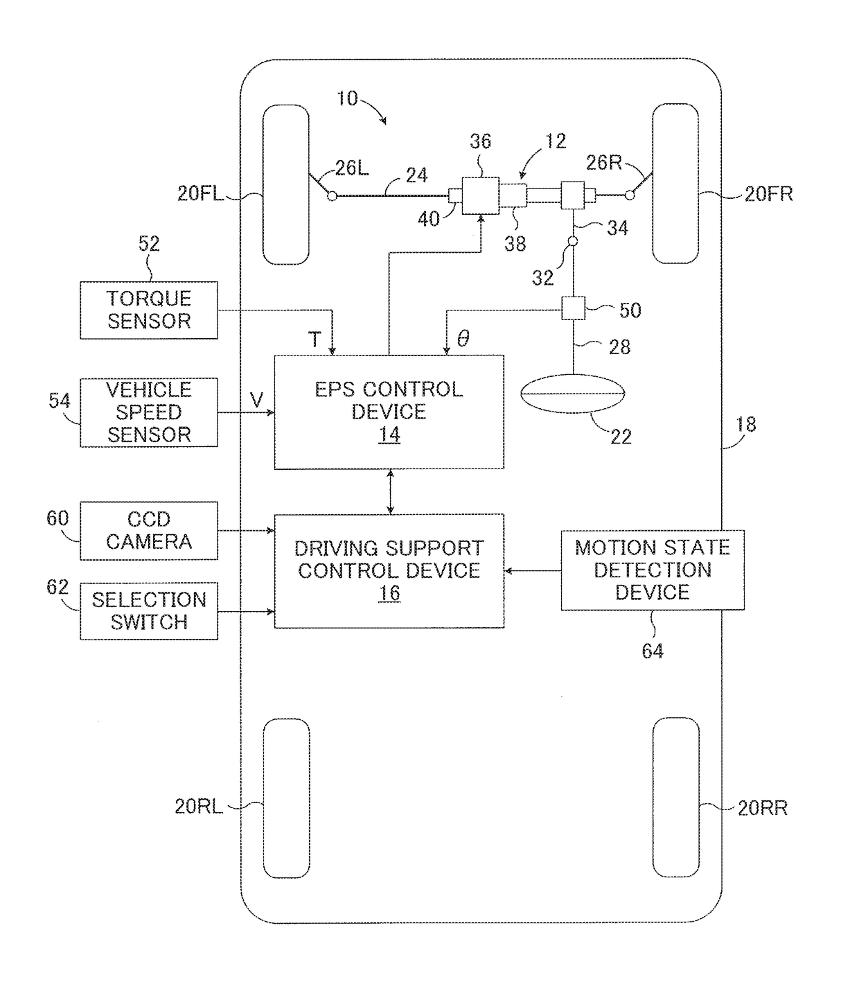
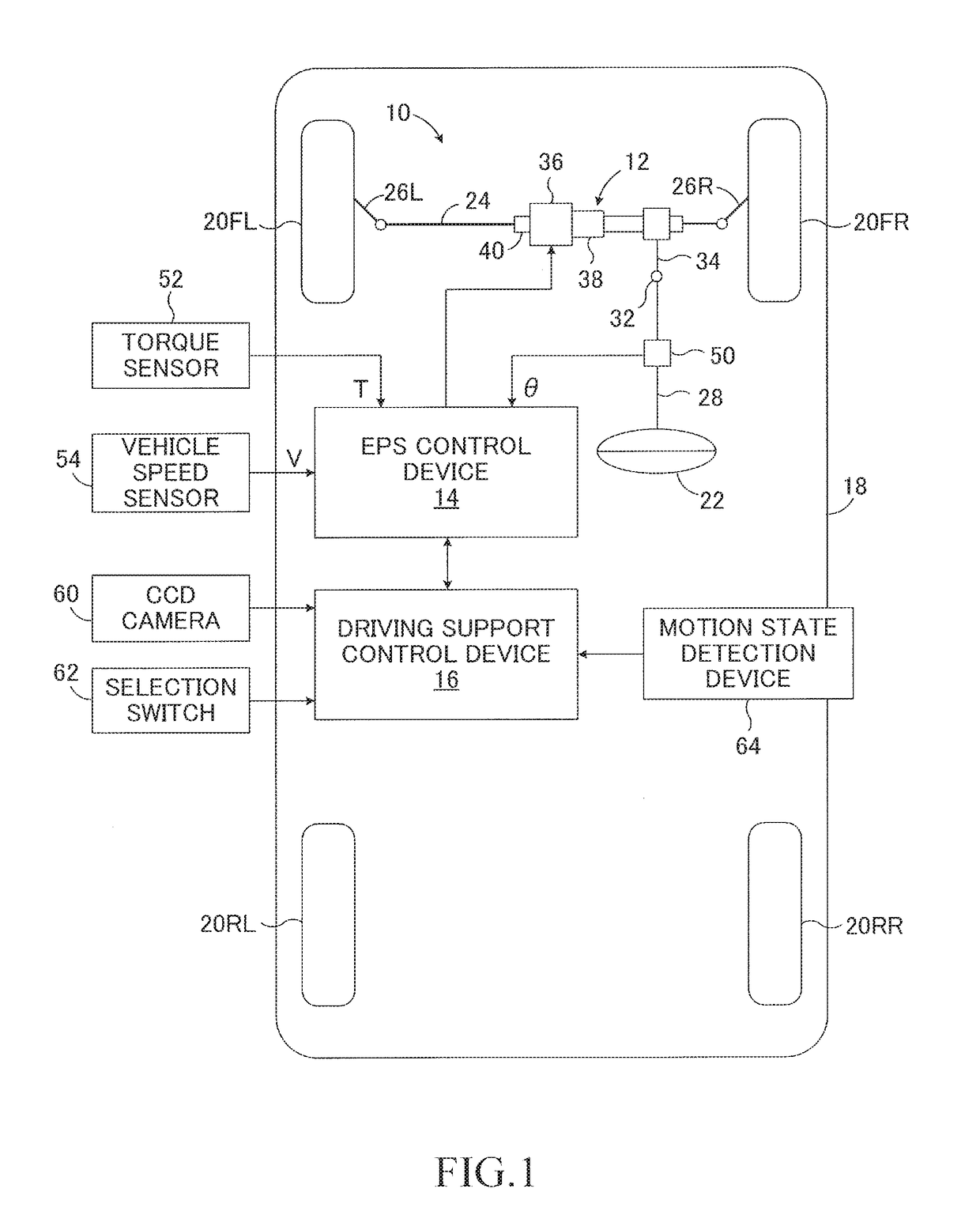
[0034]FIG. 1 is a schematic configuration diagram for illustrating a steering reaction force control apparatus 10 according to an embodiment of the present disclosure. The steering reaction force control apparatus 10 is applied to a vehicle 18 including an electric power steering (EPS) device 12, an EPS control device 14 serving as a control device configured to control the electric power steering device 12, and a driving support control device 16.

[0035]As illustrated in FIG. 1, the vehicle 18 includes front left and right wheels 20FL and 20FR, which are steered wheels, and rear left and right wheels 20RL and 20RR, which are non-steered wheels. The front wheels 20FL and 20FR are steered via a rack bar 24 and tie rods 26L and 26R by the electric power steering device 12 driven in response to an operation by a driver on a steering wheel 22. The steering wheel 22 i...


PUM


Abstract

Provided is a steering reaction force control apparatus for a vehicle including a driving support device configured to control an electric power steering device via a controller so that a steered angle of steered wheels reaches a target steered angle. When the driving support device is operating, the controller calculates a target steering spring torque based on a corrected steering angle corrected by a target steering angle for driving support control. When the magnitude of the corrected steering angle is less than a reference value, the target steering spring torque is calculated so that the magnitude of the target steering spring torque becomes larger in a case where the driving support device is operating compared with a case where the driving support device is not operating.

Description

BACKGROUND[0001]1. Technical Field[0002]The present disclosure relates to a steering reaction force control apparatus for a vehicle including an electric power steering device and a driving support device.[0003]2. Description of the Related Art[0004]A steering reaction force control apparatus for a vehicle, e.g., a motor vehicle, is configured to apply a torque to a steering device through an electric power steering device, thereby reducing a steering load imposed on a driver, and improving steering feeling. For example, as described in Japanese Patent Application Laid-open No. 2007-76582, in a steering reaction force control apparatus, a target steering reaction force torque is calculated, and an electric power steering device is controlled through PID feedback so that an actual steering reaction torque reaches the target steering reaction force torque. The target steering reaction force torque includes a target spring torque for generating a force of returning a steering wheel to ...

Claims


Application Information

Patent Timeline
Patent Type & Authority Applications(United States)
IPC IPC(8): B62D6/00B62D6/10B62D6/02B62D5/04
CPCB62D6/008B62D5/0457B62D6/002B62D6/10B62D6/02B62D5/04B62D6/00B62D15/025B62D5/0463
Inventor KUDO, YOSHIO
Owner TOYOTA JIDOSHA KK
Why Eureka
Try Eureka