Centrifugal pump impellor with novel balancing holes that improve pump efficiency

a centrifugal pump and impellor technology, applied in the direction of pump components, non-positive displacement fluid engines, liquid fuel engine components, etc., can solve the problems of loss of pump efficiency and significantly reduce the efficiency of centrifugal pumps, so as to prolong the life of the support bearing, reduce the axial thrust, and reduce the demands placed on the support bearing

Active Publication Date: 2017-03-09
FLOWSERVE PTE LTD
View PDF5 Cites 2 Cited by
  • Summary
  • Abstract
  • Description
  • Claims
  • Application Information

AI Technical Summary

Benefits of technology

[0013]The present invention is a centrifugal pump impellor having balancing holes that minimize disruption of the primary process fluid flow caused by the flow of leakage fluid through balance holes, thereby reducing axial thrust while at the same time minimizing the loss of pump efficiency caused by the balancing holes.
[0014]In one general aspect of the invention, the balancing holes penetrate the rear shroud between the blades 110, and are angled in both axial and rotational directions so as to direct the flow of leakage fluid in a direction that approximates the direction of the primary process fluid flow along the blades. As a result, the flow of leakage fluid causes little if any interfere with the flow of process fluid along the blades. This improves the pump efficiency as compared to similar pumps having balancing holes that are directed axially through the rear shroud.
[0015]In a second general aspect of the present invention, the balancing holes extend from the rear cavity through the rear shroud and within the impellor blades, exiting through the leading edges of the impellor blades. The leakage flow through the balance holes thereby enters the primary flow in locations where the process fluid is almost static in relation to the blades, and is not flowing along the sides of the blades. This minimizes the impact of the leakage fluid on the flow of the process fluid past the blades, and thereby minimizes the loss of pump efficiency caused by the balance holes. In fact, the leakage flow exiting the impeller vane leading edges enters the primary flow in a way that disrupts boundary layer flow along the vanes, thereby reducing flow losses and improving efficiency. In embodiments, the leading edge of each blade includes a plurality of openings through which leakage fluid emerges into the primary process fluid flow. In some of these embodiments, the openings are all connected to a single balancing hole that extends sideways through the blade and through the rear shroud to the rear cavity.

Problems solved by technology

While balancing holes are effective in reducing axial thrust, they also inevitably cause a loss of pump efficiency.
Accordingly, the flow of leakage fluid significantly perturbs and interferes with the primary flow 102 of the process fluid, thereby significantly reducing the efficiency of the centrifugal pump.

Method used


Image

  • Centrifugal pump impellor with novel balancing holes that improve pump efficiency
  • Centrifugal pump impellor with novel balancing holes that improve pump efficiency
  • Centrifugal pump impellor with novel balancing holes that improve pump efficiency

Examples


Embodiment Construction

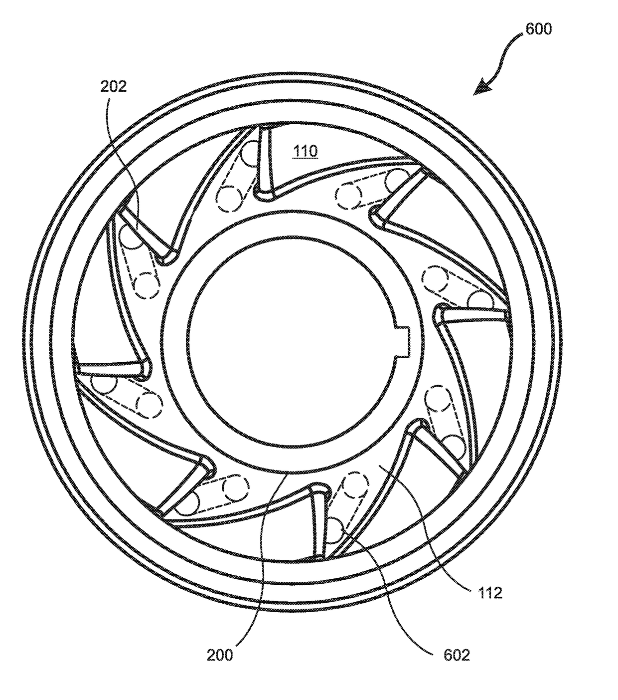
[0043]The present invention is a centrifugal pump impellor having balancing holes that minimize disruption of the process fluid flow along the blades due to the flow of leakage fluid through balancing holes, thereby reducing axial thrust while minimizing the loss of pump efficiency caused by the balancing holes.

[0044]With reference to FIG. 6, in one general aspect of the invention the balancing holes 602 penetrate the rear shroud 112 between the blades 110 and are angled in both axial and rotational directions so as to direct the flow of leakage fluid 402 through the balancing holes 602 in a direction that is approximately parallel to the primary flow 102 of process fluid along the blades 110. As a result, the flow 102 of the process fluid along the blades 110 is only minimally disturbed, if at all, by the flow of leakage fluid 402 from the rear cavity 304. This improves the pump efficiency as compared to conventional pumps with axially directed balancing holes 400 through which lea...


PUM


Abstract

A centrifugal pump impellor includes balancing holes that reduce axial thrust while minimizing the loss of pump efficiency. In one general aspect, the balancing holes penetrate the rear shroud between the blades, and are angled in both axial and rotational directions so as to direct the leakage fluid approximately parallel to the primary process fluid, so that it causes minimal interference with the primary fluid flow. In a second general aspect, the balancing holes extend from the rear cavity within the impellor blades and through the leading edges of the blades, thereby entering the primary flow in locations where the process fluid is almost static relative to the blades. This minimizes the impact on the flow of the process fluid past the blades, and thereby minimizes the loss of pump efficiency caused by the balance holes. In embodiments, each blade leading edge includes a plurality of balancing hole outlets.

Description

RELATED APPLICATIONS[0001]This application is a divisional application of U.S. application Ser. No. 14 / 220,169, filed Mar. 20, 2014, which is herein incorporated by reference in its entirety for all purposes.FIELD OF THE INVENTION[0002]The invention relates to centrifugal pumps, and more particularly, to centrifugal pump impellors that include balancing holes to reduce axial thrust.BACKGROUND OF THE INVENTION[0003]Centrifugal pumps are the most widely used pumps in the world. While there are many variations and configurations, with reference to FIG. 1 all such pumps 100 include an impellor 106 mounted on a shaft 108 that rotates the impellor 106 continuously within a housing 116. The impellor 106 includes a plurality of “blades” or “vanes”110 extending outward from a hub and a central “eye” of the impellor. Process fluid 102 entering through an inlet 118 to the eye is caused to rotate by the impellor blades 110, and is driven by centrifugal force toward the perimeter of the impellor...

Claims


Application Information

Patent Timeline
Patent Type & Authority Applications(United States)
IPC IPC(8): F04D29/22F04D29/40
CPCF04D29/40F04D29/2266
Inventor ELEBIARY, KARIEMJUDGE, SCOTTMORLAC, EDOUARDO'SULLIVAN, MARK
Owner FLOWSERVE PTE LTD
Why Eureka
Try Eureka