Control circuit and control method for a synchronous machine

Active Publication Date: 2017-03-09
DENTSPLY SIRONA INC
View PDF17 Cites 2 Cited by
  • Summary
  • Abstract
  • Description
  • Claims
  • Application Information

AI Technical Summary

Benefits of technology

[0028]Repeated measurement makes it possible to prevent errors. For this purpose, measuring can occur several times sequentially after clamping, and a change between the measured values can be determined. If the change is minimal from measured value to

Problems solved by technology

This renders long interruptions in the power supply to the synchronous

Method used


Image

  • Control circuit and control method for a synchronous machine
  • Control circuit and control method for a synchronous machine
  • Control circuit and control method for a synchronous machine

Examples


Embodiment Construction

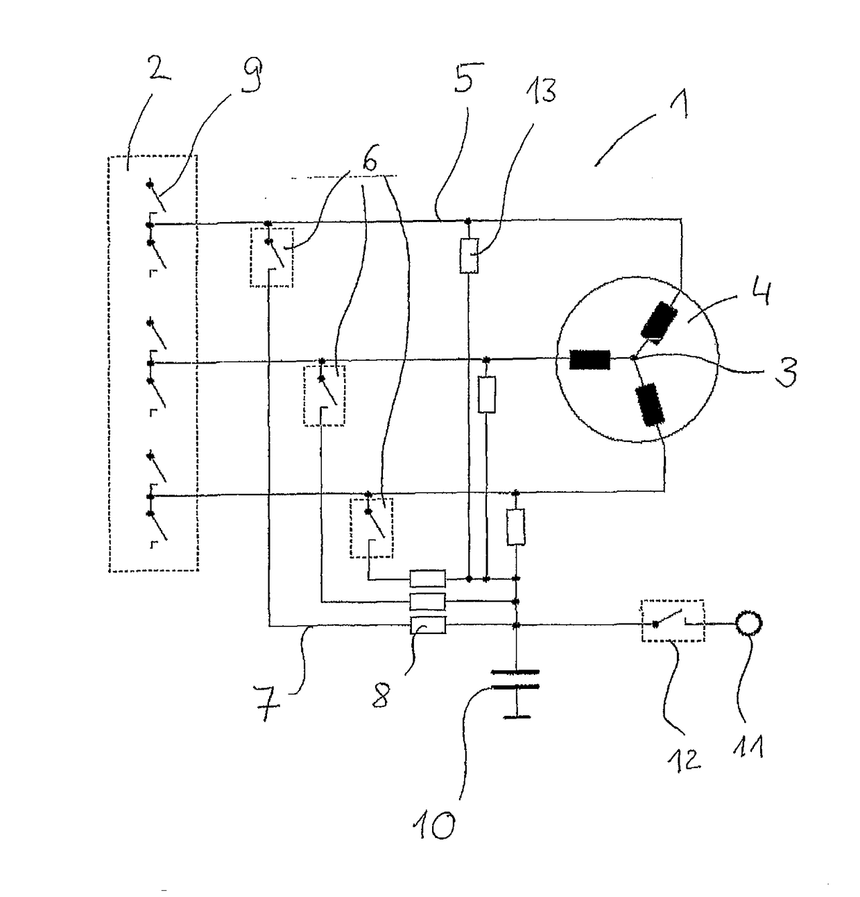
[0033]FIG. 1 shows a synchronous machine 1 with a voltage supply 2 designed as a full bridge, and three stator windings 4 connected in a star 3. The full bridge 2 is connected to a stator winding 4 via a lead 5. A clamping circuit 7 is attached to the lead 5 via a clamp and switch 6.

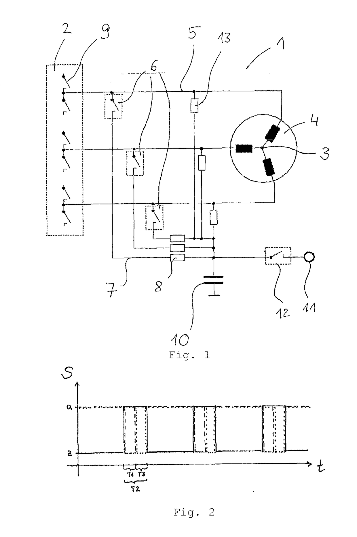
[0034]The switching and sampling states S of a method for measuring the angular position of a rotor are schematically portrayed in FIG. 2, wherein a closed switching state or sampling state is identified with “z,” and an open switching state or non-sampling is identified with “a.” The power supply is interrupted by the full bridge 2. For this purpose, the power supply can, for example, have switches 9, the switching state of which is depicted as a solid line. In this phase, the synchronous machine 1 more or less runs as a generator. A voltage generated by an induction current overlaps the voltage generated by this generator, however. To establish an unpowered state as quickly as possible, the clamping ci...


PUM


Abstract

The invention relates to a control circuit for a synchronous machine (1) of a dental handpiece, comprising a voltage supply (2) and a clamping circuit (7) connected by switches (6). The invention also relates to a method for determining an angular position of a rotor of a synchronous machine (1), wherein a power supply is switched off for a total period of time (T2), a clamping circuit (7) is connected for a time interval (T1), whereupon an electromotive force is measured, and the angular position is determined from the electromotive force.

Description

[0001]The invention relates to a control circuit for a synchronous machine of a dental handpiece having a voltage supply, as well as a method for determining the angular position of the rotor of a synchronous machine for controlling the rotational speed of the synchronous machine.PRIOR ART[0002]Synchronous motors are known as electrical drives, such as for dental handpieces, i.e., synchronous machines operated with a motor, in which a rotor in the stator runs in sync with a moved rotary field.[0003]To control such a synchronous machine, it is further known to determine the position of the rotor relative to the rotating stator field during operation. It is known, for example, from DE 195 27 982 AI to provide sensors for this purpose.[0004]A disadvantage is that such a sensor constitutes an additional expense, and that integrating a sensor—for example, in a dental handpiece—can be problematic, given the hygienic requirements.[0005]Another option for determining the rotor position is t...

Claims


Application Information

Patent Timeline
IPC IPC(8): H02P6/182
CPCH02P6/182
Inventor ALTENDORF, HANS-WALTERHILL, VOLKER
Owner DENTSPLY SIRONA INC
Why Eureka
Try Eureka