Printing apparatus, paper supply apparatus, and paper supply method

Active Publication Date: 2017-03-16
NIPPON PRIMEX
View PDF3 Cites 0 Cited by
  • Summary
  • Abstract
  • Description
  • Claims
  • Application Information

AI Technical Summary

Benefits of technology

The invention aims to make it simple to transmit each paper sheet from multiple paper rolls to a printing part. This results in a more efficient and effective printing process.

Problems solved by technology

However, because the printing apparatuses disclosed in Japanese Unexamined Patent Application Publication No. 2006-341989 and Japanese Unexamined Patent Application Publication No. 2001-105676 require the dedicated paths for each paper roll, components such as a roller and a sensor were required for the dedicated paths, and spaces for installing the components are required.

Method used


Image

  • Printing apparatus, paper supply apparatus, and paper supply method
  • Printing apparatus, paper supply apparatus, and paper supply method
  • Printing apparatus, paper supply apparatus, and paper supply method

Examples


Embodiment Construction

1. Configuration of a Printer

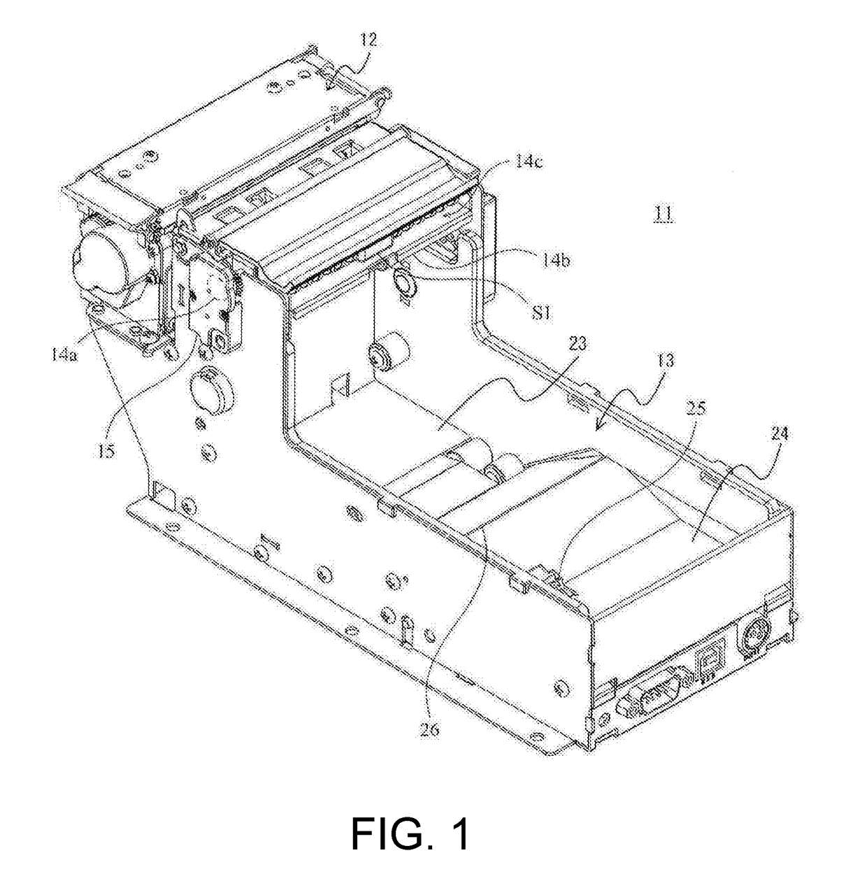
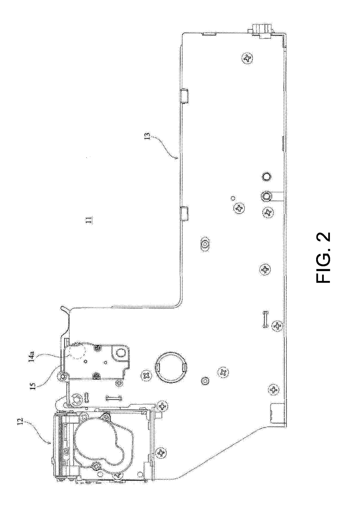
[0032]A configuration of a printer 11 that is an example of a printing apparatus according to the present invention is explained with reference to FIGS. 1 to 14. FIG. 1 shows a perspective view of the printer 11 according to one exemplary embodiment of the present invention. FIG. 2 shows a right side view of the printer 11. FIG. 3 shows a left side view of the printer 11. FIG. 4 shows a plane view of the printer 11. FIG. 5 shows a bottom view of the printer 11. FIG. 6 shows a back view of the printer 11. FIG. 7 shows a front view of the printer 11. FIG. 8 shows a perspective view of a longitudinal section of the printer 11 as seen from the right side. FIG. 9 shows a longitudinal section of the printer 11 as seen from the right side. FIG. 10 shows a perspective view of a longitudinal section of the printer 11 as seen from the left side. FIG. 11 shows a longitudinal section of the printer 11 as seen from the left side. FIG. 12 shows a state where a paper f...


PUM

PropertyMeasurementUnit
Speedaaaaaaaaaa
Frictional forceaaaaaaaaaa

Abstract

A printer includes a first housing part, a second housing part, a printing part that prints on the first paper sheet and the second paper sheet, a conveying part that includes a holding part that is configured to hold the overlapping first paper sheet and the second paper sheet respectively pulled out from a first paper roll and a second paper roll, and conveys the first paper sheet out of the first paper sheet and the second paper sheet held by the holding part to the printing part, a first paper sheet sensor that detects the presence of the first paper sheet, and a controlling part that makes the conveying part convey the second paper sheet held by the holding part to the printing part when the first paper sheet sensor detects that there is no first paper sheet to be conveyed to the printing part.

Description

CROSS-REFERENCE TO RELATED APPLICATIONS[0001]The present application is a continuation application of International Application number PCT / JP2015 / 056907, filed on Mar. 10, 2015, which claims priority under 35 U.S.C §119(a) to Japanese Patent Application No. 2014-120041, filed on Jun. 10, 2014. The content of this application is incorporated herein by reference in their entirety.BACKGROUND OF THE INVENTION[0002]The present invention relates to a printing apparatus, a paper supply apparatus, and a paper supply method for printing on a paper sheet pulled out from a plurality of paper rolls.[0003]A printing apparatus that houses, for example, two paper rolls and prints on a paper sheet pulled out from each paper roll with a printing part is used as a printing apparatus for printing on a paper roll. In this printing apparatus, a conveyance path and a discharging part dedicated for a paper sheet pulled out from each of the paper rolls are provided.[0004]Conventionally, a method for sharin...

Claims


Application Information

Patent Timeline
IPC IPC(8): B41J13/00
CPCB41J13/0009B41J11/0095B41J15/042B65H20/02B65H16/021B65H16/028B65H2301/4128B65H2301/4137B65H2301/41392B65H2404/722B65H2511/51B65H2511/515B65H2513/512B65H2701/1311B65H2701/1936B65H2801/12B41J15/18B65H5/28B65H19/12
Inventor SATO, HITOSHIOMORI, MANABU
Owner NIPPON PRIMEX
Why Eureka
Try Eureka