Method For Operating An Oil Circuit, In Particular For A Vehicle

a technology of oil circuit and oil circuit, which is applied in the direction of machines/engines, mechanical equipment, engine load, etc., to achieve the effect of simple operation, reduced fuel consumption of internal combustion engines, and reduced fuel consumption

Active Publication Date: 2017-03-16
MAN TRUCK & BUS AG
View PDF11 Cites 7 Cited by
  • Summary
  • Abstract
  • Description
  • Claims
  • Application Information

AI Technical Summary

Benefits of technology

[0006]It is an object of the invention to provide a method for operating an oil circuit, in particular for a vehicle, and a device for a vehicle, in particular for a commercial vehicle, by which the fuel consumption of the internal combustion engine can be reduced in a simple and effective manner.
[0007]In accordance with one aspect of the invention, a method for operating an oil circuit, in particular for a vehicle, is proposed, whereby by the oil circuit an internal combustion engine is supplied with oil, whereby the oil circuit comprises at least one oil cooler, by which the oil flowing through the oil circuit is cooled, and wherein at least one temperature sensor is provided, by which the temperature of the oil flowing through the oil circuit is measured, in particular downstream of the oil cooler and upstream of the internal combustion engine. According to an aspect of the invention, the temperature sensor is connected for signaling purposes to a regulating and / or control device, by which the temperature of the oil flowing through, the oil circuit is controlled and / or regulated such that the temperature measured by the temperature sensor has a defined target temperature value. In addition, in particular for reducing the fuel consumption of the internal combustion engine, the target temperature value is adjusted and / or displaced by the regulating and / or control device as a function of the drive power, in particular as a function of the drive torque and / or as a function of the drive revolution rate, of the internal combustion engine.
[0008]In this way the fuel consumption of the internal combustion engine can be reduced simply and effectively, because the temperature of the oil flowing through the oil circuit in the region of the temperature sensor is now adjusted or changed by the regulating and / or control device as a function of the drive power of the internal combustion engine. For example, at a lower drive power of the internal combustion engine a higher target temperature value can be set. As a result, the viscosity of the oil and hence also the fuel consumption of the internal combustion engine is reduced. Owing to the low drive power of the internal combustion engine, the oil is also not heated in the region of the internal combustion engine so much that it is damaged. At a greater drive power of the internal combustion engine, for example, a lower target temperature value can be set or adjusted by the regulating and / or control device. As a result, it is ensured that the oil is not heated greatly by the internal combustion engine so that it is decomposed. With the procedure according to the invention, the temperature of the oil flowing through the oil circuit can thus always be set such that the internal combustion engine has a minimal fuel consumption. As a result, the harmful emissions emitted by the internal combustion engine can be reduced.

Problems solved by technology

Owing to the low drive power of the internal combustion engine, the oil is also not heated in the region of the internal combustion engine so much that it is damaged.

Method used


Image

  • Method For Operating An Oil Circuit, In Particular For A Vehicle
  • Method For Operating An Oil Circuit, In Particular For A Vehicle
  • Method For Operating An Oil Circuit, In Particular For A Vehicle

Examples


Embodiment Construction

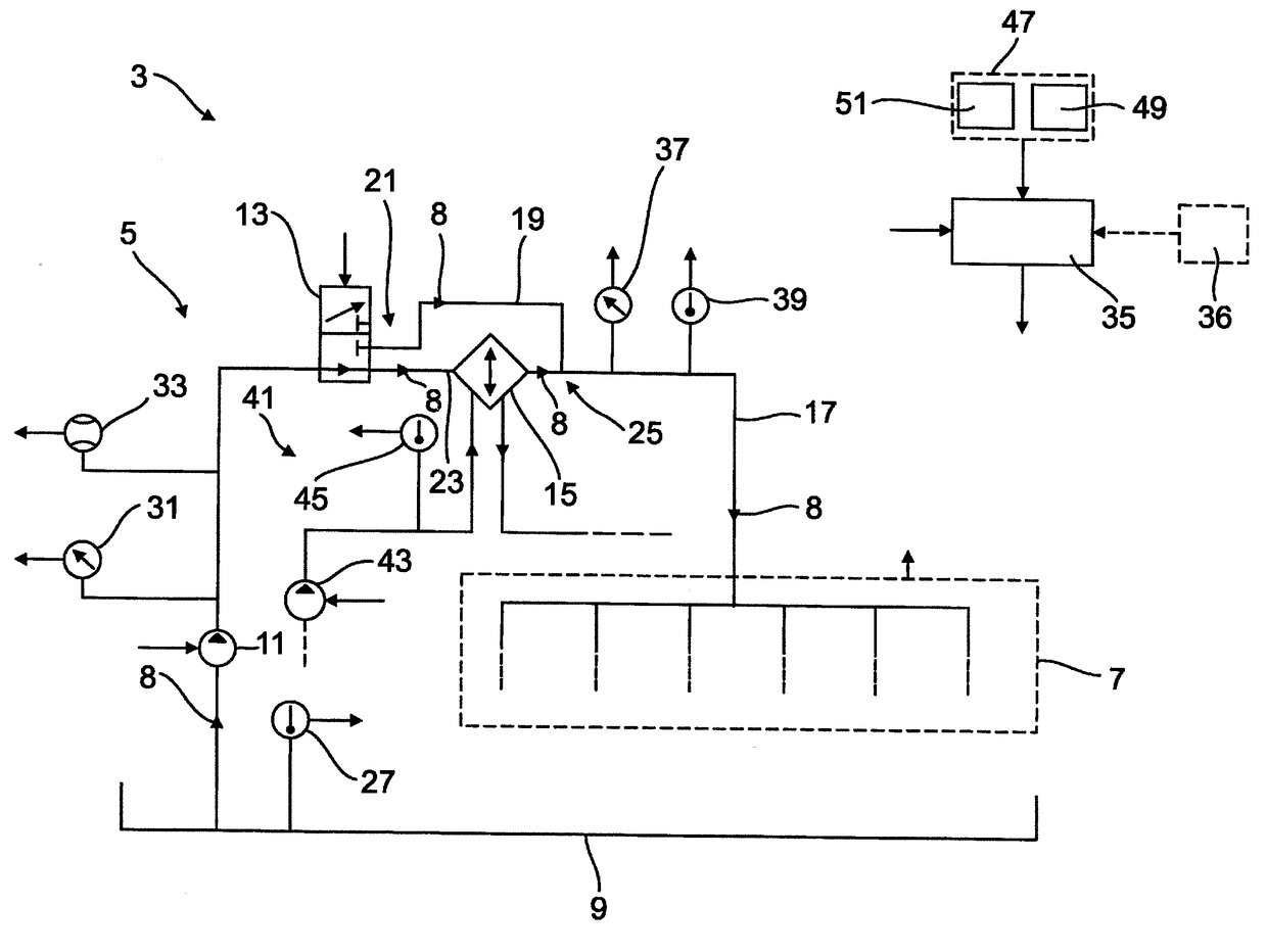
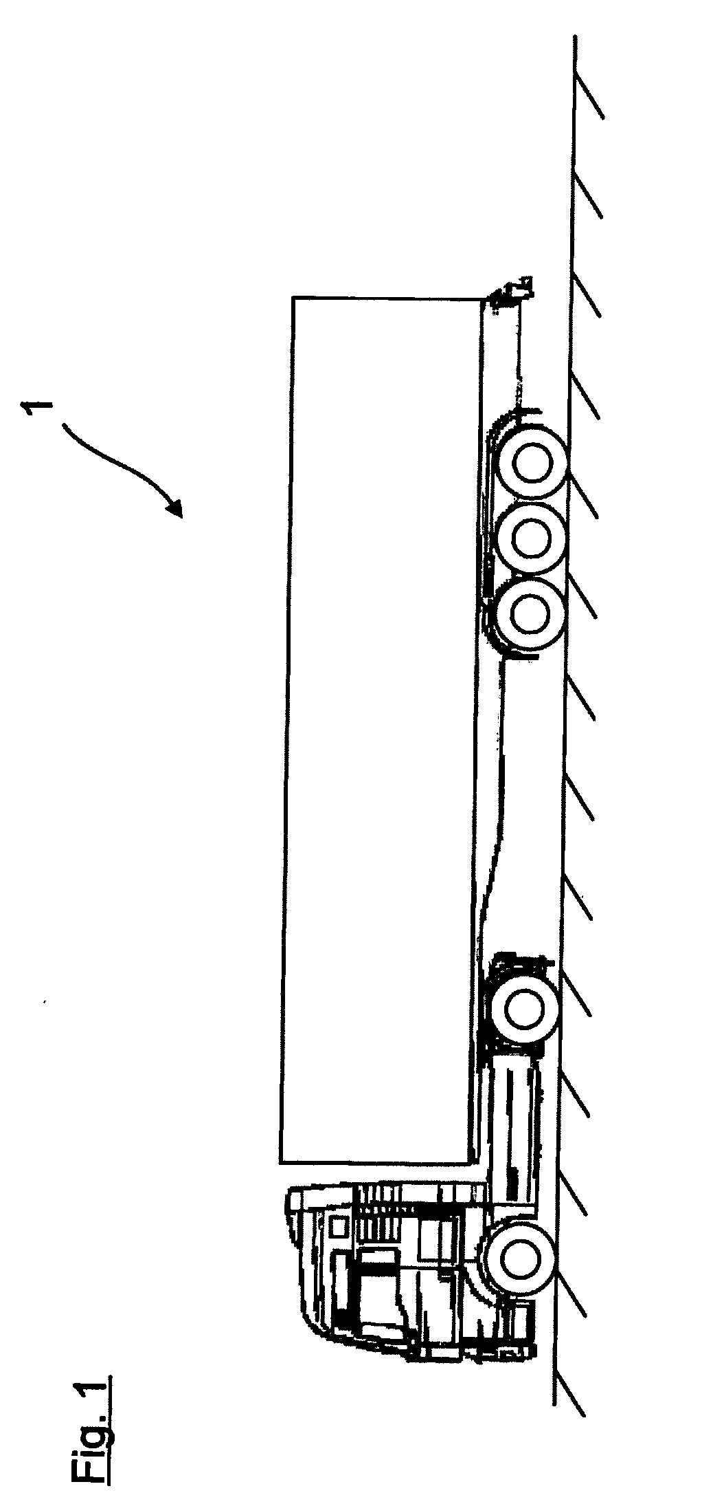
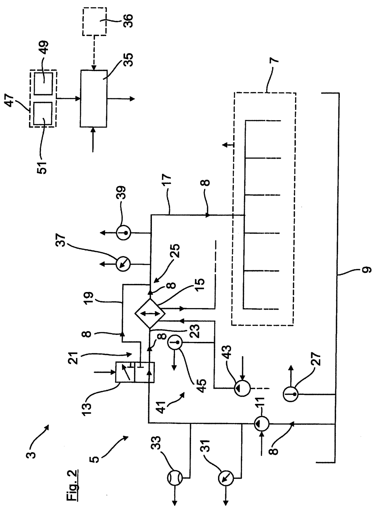
[0037]In FIG. 1 a vehicle 1, here by way of example in the form of a truck, with a device 3 according to the invention (FIG. 2) is shown. The design of the device 3 is described in detail below using FIG. 2:

[0038]As is shown in FIG. 2, the device 3 comprises an oil circuit 5, by which an internal combustion engine 7, indicated in FIG. 2 with dashed lines, is supplied with oil 8. The oil circuit 5 comprises here by way of example an oil sump 9, an oil pump 11, a directional control valve 13, an oil cooler 15 and a main channel 17 when looking in the direction of flow of the oil. By the oil pump 11, the oil 8 that is collected in the oil sump 9 is sucked in and transported in the further oil circuit 5. The directional control valve 13, here by way of example in the form of a 3 / 2 directional control valve, forms an actuator, by which the amount of oil 8 that is passed by the oil cooler 15 and the amount of oil 8 flowing through a bypass channel 19 of the oil circuit 5 can be set or adj...


PUM


Abstract

A method for operating an oil circuit for a vehicle, the oil circuit being configured to supply oil to an internal combustion engine, wherein the oil circuit includes an oil cooler, and wherein at least one temperature sensor measures the temperature of the oil flowing through the oil circuit, downstream of the oil cooler and upstream of the internal combustion engine, the temperature sensor being connected for signaling purposes to a regulating and / or control device, includes: controlling and / or regulating, by the regulating and / or control device, the temperature of the oil flowing through the oil circuit, such that the temperature measured by the temperature sensor has a defined target temperature value; and setting and / or adjusting, by the regulating and / or control device, as a function of a drive power of the internal combustion engine, the defined target temperature value so as to reduce fuel consumption of the internal combustion engine.

Description

BACKGROUND OF THE INVENTION[0001]1. Field of the Invention[0002]The invention relates to a method for operating an oil circuit, in particular for a vehicle, a device for a vehicle, in particular for a commercial vehicle, and a vehicle, in particular a commercial vehicle, for performing the method and / or with the device.[0003]2. Description of the Related Art[0004]An internal combustion engine is usually supplied with oil by an oil circuit. The oil can be used in this case for both lubricating the internal combustion engine and also for cooling the internal combustion engine. Such an oil circuit regularly comprises at least one oil cooler, by which the oil flowing through the oil circuit is cooled. The oil cooler is often in the form of a heat absorbing heat exchanger of a coolant circuit, by which both the internal combustion engine and also the oil flowing through the oil circuit can be cooled.[0005]Furthermore, the oil circuit usually also comprises at least one temperature sensor...

Claims


Application Information

Patent Timeline
Patent Type & Authority Applications(United States)
IPC IPC(8): F01M5/00F01P11/08
CPCF01M5/005F01P11/08F01M2250/62F01M2250/60F01M5/002F01P7/167F01P2025/64F01P2025/60F01P2025/40F01M2005/004F01P7/14
Inventor RITTER, JURGEN
Owner MAN TRUCK & BUS AG
Why Eureka
Try Eureka