Illuminating Ventilator

a ventilator and light technology, applied in the field of illumination ventilators, can solve the problems of inconvenient installation complicated design of conventional illuminating ventilators, and significant complicated installation, and achieve the effects of convenient maintenance or repair of illuminating ventilators, reduced production costs, and convenient installation of illuminating ventilators

Active Publication Date: 2017-03-16
SUNONWEALTH ELECTRIC MACHINE IND
View PDF0 Cites 12 Cited by
  • Summary
  • Abstract
  • Description
  • Claims
  • Application Information

AI Technical Summary

Benefits of technology

[0012]It is therefore the objective of this invention to provide an illuminating ventilator having a power supply module electrically connected to a fan and a lamp separately. As such, installation convenience of the illuminating ventilator is improved, and maintaining and repairing difficulties thereof are reduced.
[0027]With the arrangements described above, it merely requires connecting the AC input of the power supply module to an external power source which generates the electrical power required for the fan and the lamp. Thus, the installation of the illuminating ventilator is convenient, and the production cost is reduced. Furthermore, since the case needs not be uninstalled when inspecting and repairing the lamp or the power supply module, it is convenient to maintain or repair the illuminating ventilator.

Problems solved by technology

However, before installing said recessed lamp or ventilator, a corresponding installation hole must be formed in the ceiling for the recessed lamp or ventilator to be installed therein.
The formation of the installation hole adversely affects the appearance of the space wherein the recessed lamp or ventilator is arranged, and even makes the installation significantly complicated.
Specifically, the connection process for settling each power supply unit includes complicated steps such as arranging wires, removing insulating layers of the wires, winding the wires together, rewrapping the wires with insulating materials (e.g. insulating tape), and packing the wires.
Since such connection process must be done twice to separately connect the power supply units of the ventilator and the lamp to the electrical power grid, the installation of the conventional illuminating ventilator is inconvenient.
According to the above, in this type of conventional illuminating ventilator, the power supply units of the ventilator and the lamp can be connected to the same power input, but the design thereof is rather complicated.
Besides, such a conventional illuminating ventilator requires additional insulating component and separating member, thus resulting in a high production cost.
Furthermore, since the ventilator and the lamp are combined together, when a component of either the ventilator, the lamp or the power supply units of them needs to be repaired or inspected, the repairer must uninstall the entire illuminating ventilator for repairing or inspecting said component.
Hence, it is hard to maintain and repair the conventional illuminating ventilator.
In addition, with the inconvenience as described above in the installation of the conventional illuminating ventilator, the repairer has to face said inconvenience again when reinstalling the illuminating ventilator after inspecting and repairing processes.

Method used


Image

  • Illuminating Ventilator
  • Illuminating Ventilator
  • Illuminating Ventilator

Examples


Embodiment Construction

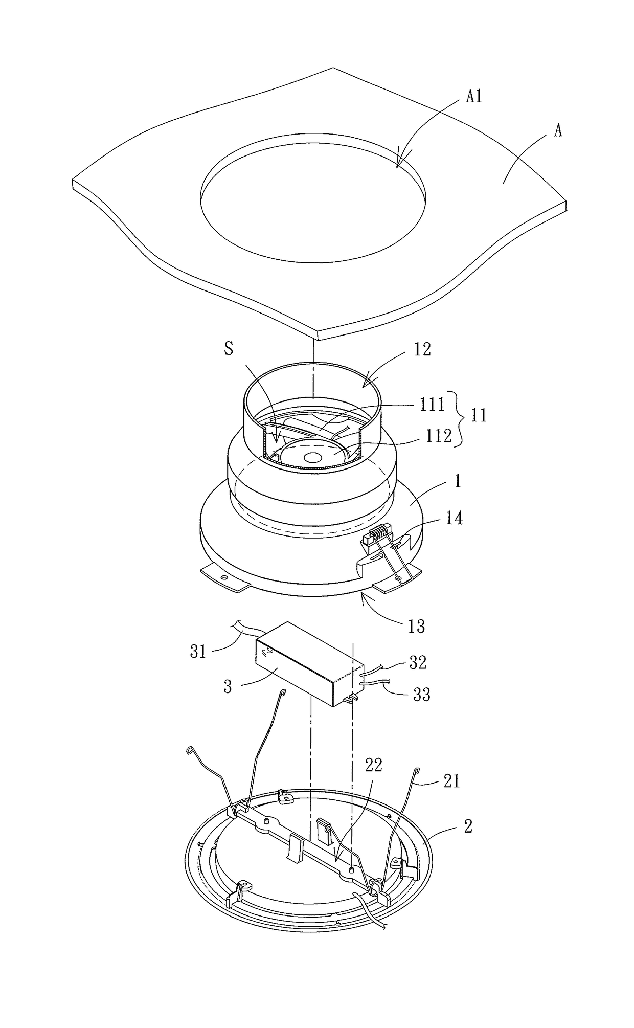
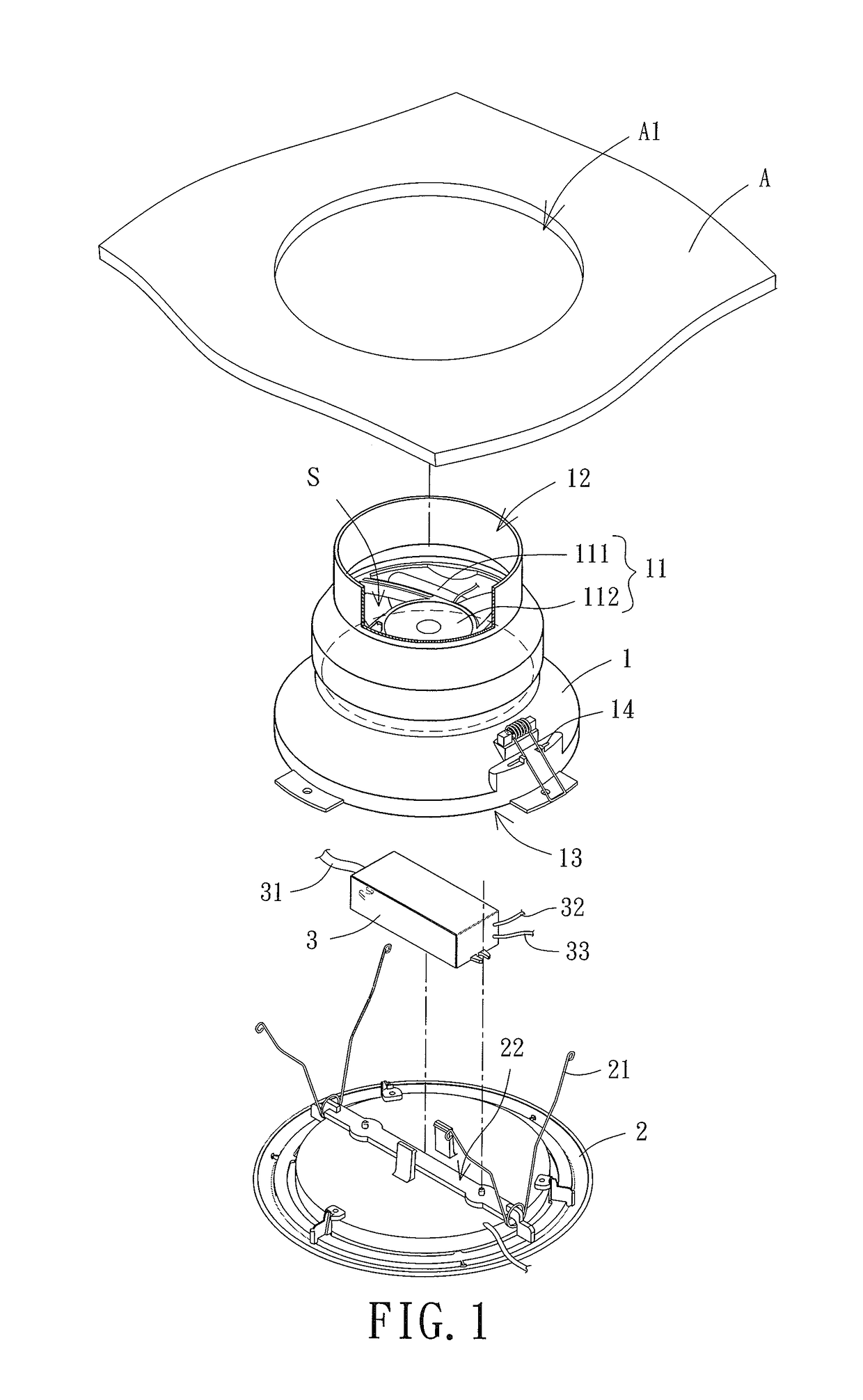
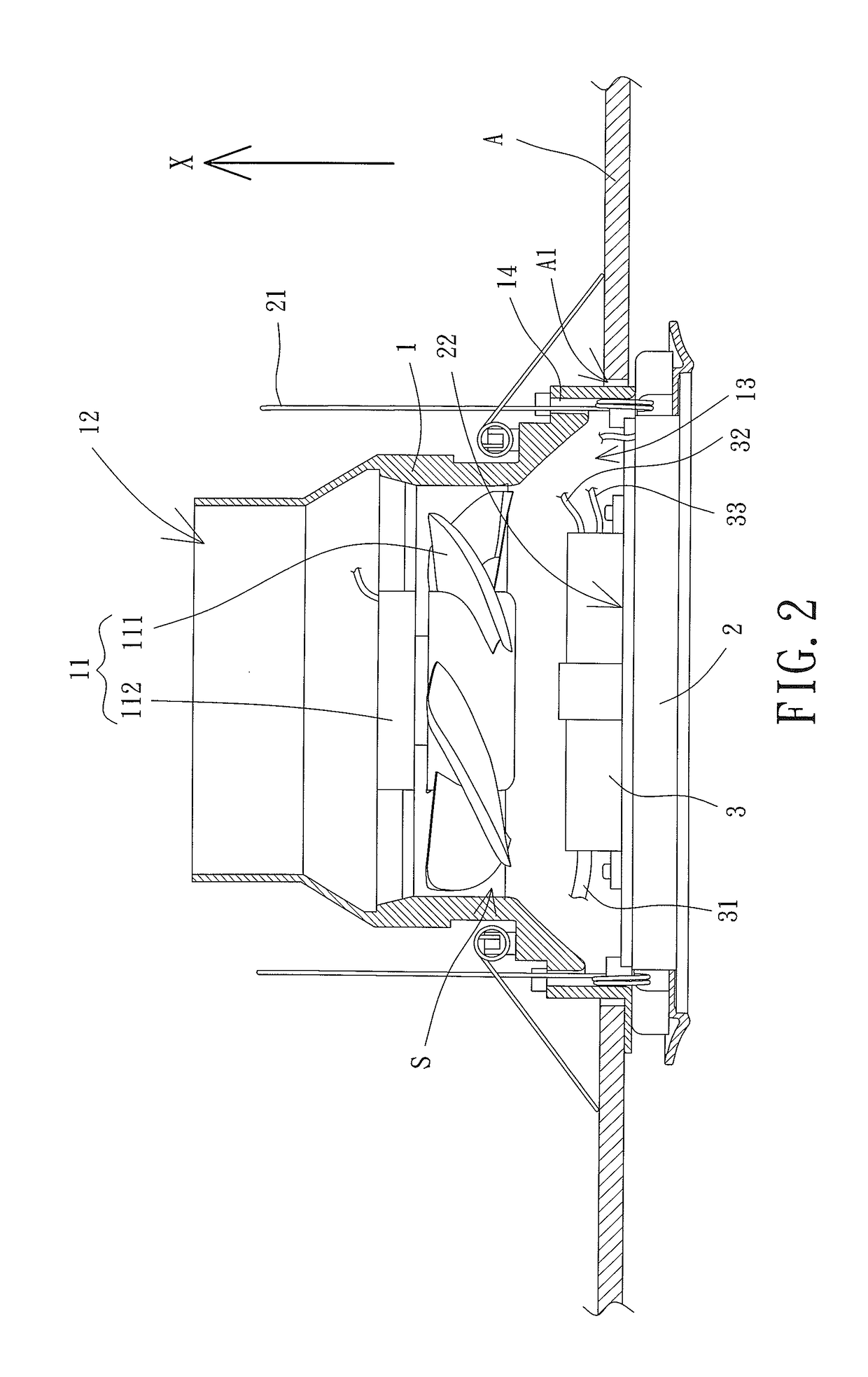
[0037]Please refer to FIGS. 1 and 2, an illuminating ventilator according to a first embodiment of the present disclosure includes a case 1, a lamp 2 and a power supply module 3. The lamp 2 is detachably attached to the case 1. A fan 11 is disposed in the case 1. The power supply module 3 is electrically connected with the fan 11 and the lamp 2 separately.

[0038]In this embodiment, the fan 11 can be an axial flow fan. Alternatively, the fan 11 can be a blowing fan, which is not limited in the present disclosure. The fan 11 includes a fan wheel 111 and a base 112, and the fan wheel 111 can be coupled with the base 112. A first air opening 12 and a second air opening 13 are formed on two sides of the case 1, respectively. The case 1 includes an air channel S having two ends respectively communicating with the first and second air openings 12, 13, with the fan 11 received in the air channel S. Besides, the first and second air openings 12, 13 can communicate with an outlet and an inlet ...


PUM


Abstract

The present disclosure provides an illuminating ventilator including a case, a lamp and a power supply module. A first air opening and a second air opening are respectively formed on two sides of the case. The case includes an air channel having two ends respectively communicating with the first air opening and the second air opening. The fan is disposed in the case and is arranged in the air channel. The lamp is detachably attached to the case. The power supply module includes an AC input terminal, a first DC output terminal and a second DC output terminal. The first DC output terminal is electrically connected with the fan, and the second DC output terminal is electrically connected with the lamp. As such, the illuminating ventilator is provided with improved installation convenience, reduced production cost and reduced difficulty of maintaining and repairing.

Description

CROSS REFERENCE TO RELATED APPLICATIONS[0001]The application claims the benefit of Taiwan application serial No. 104130287, filed on Sep. 14, 2015, and the subject matter of which is incorporated herein by reference.BACKGROUND OF THE INVENTION[0002]1. Field of the Invention[0003]The present invention generally relates to an illuminating ventilator and, more particularly, to an illuminating ventilator having a power supply module.[0004]2. Description of the Related Art[0005]Illuminating devices (e.g. recessed lamp) and ventilating devices (e.g. ventilator) are usually installed into a hollow opening in a ceiling to avoid affecting the appearance of an indoor space. Such illuminating device and ventilating device are disclosed in Taiwanese patents, such as Taiwan Patents No. 581206 and M316334, respectively.[0006]However, before installing said recessed lamp or ventilator, a corresponding installation hole must be formed in the ceiling for the recessed lamp or ventilator to be install...

Claims


Application Information

Patent Timeline
Patent Type & Authority Applications(United States)
IPC IPC(8): F21V33/00F24F13/078F21V23/06F21V23/00F21V23/02F21S8/02
CPCF21V33/0096F21V23/02F21S8/026F21Y2115/10F21V23/001F24F13/078F21V23/06
Inventor HORNG, ALEXYIN, TSO-KUOSHAN, DUO-NIAN
Owner SUNONWEALTH ELECTRIC MACHINE IND
Why Eureka
Try Eureka