Image forming apparatus

a technology of forming apparatus and forming chamber, which is applied in the direction of electrographic process apparatus, instruments, optics, etc., can solve the problems of increasing the operation burden of users, requiring a number of components and a cost, and the main body of the apparatus becomes large, so as to reduce the size of the main body and the number of components

Active Publication Date: 2017-03-16
SHARP KK
View PDF11 Cites 3 Cited by
  • Summary
  • Abstract
  • Description
  • Claims
  • Application Information

AI Technical Summary

Benefits of technology

[0008]Therefore, it is a primary object of the present invention to provide an image form...

Problems solved by technology

However, this requires a large space in the horizontal direction in order to ensure a space between the developing unit and the photoreceptor drum, there is a problem that the apparatus main body becomes large.
However, in the image forming apparatus of the patent literature 1, in order to turn the developing unit with using the turning...

Method used


Image

  • Image forming apparatus
  • Image forming apparatus
  • Image forming apparatus

Examples


first embodiment

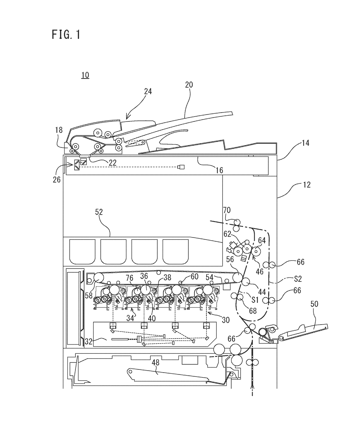
[0028]FIG. 1 is a schematic structure view viewing an entire image forming apparatus 10 that is an embodiment of the present invention from the front.

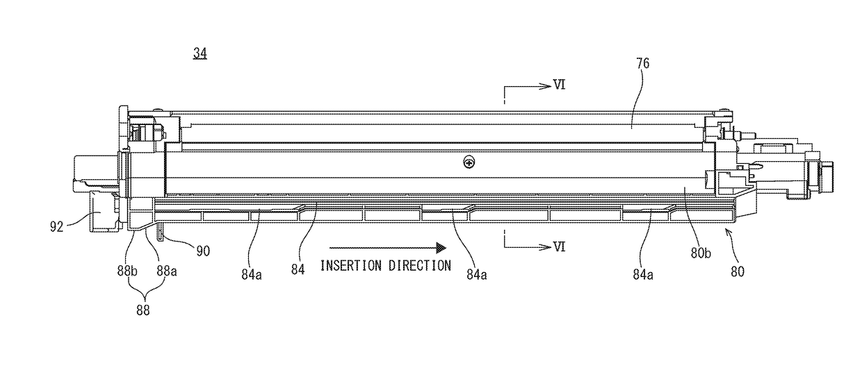
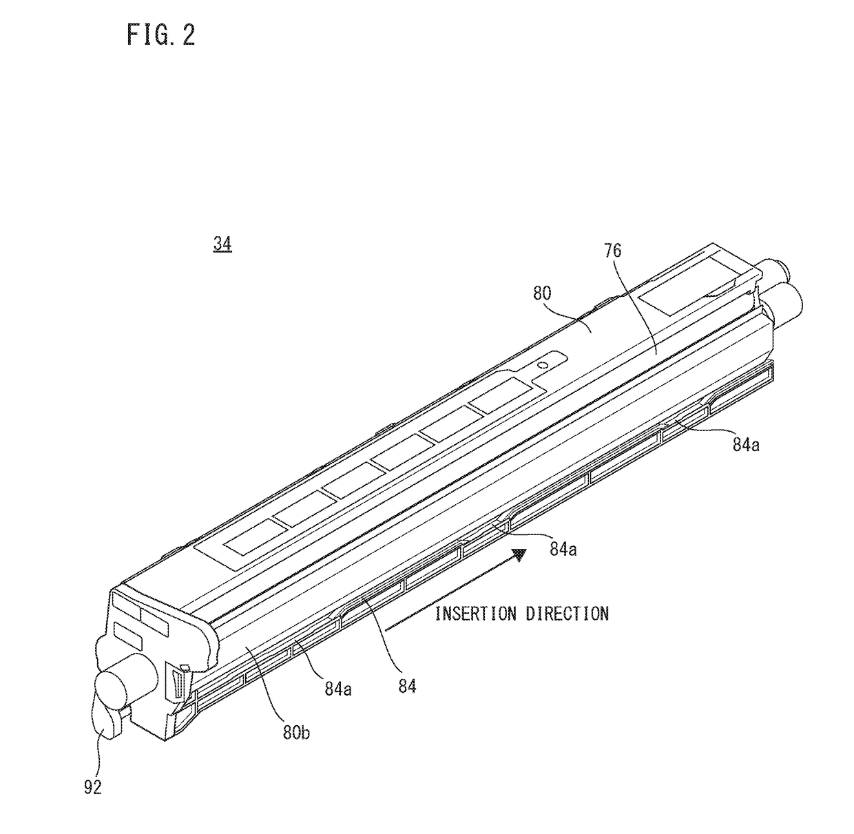
[0029]With referring to FIG. 1, the image forming apparatus 10 of the first embodiment is a multifunction peripheral (MFP) that has a copying function, a printer function, a scanner function, a facsimile function, etc., and forms a multicolor or monochromatic image on a paper (recording medium) with an electrophotographic system. As described later in detail, the image forming apparatus 10 comprises a photoreceptor unit comprising a photoreceptor drum 36 etc., and a developing unit 34 comprising a developing roller 76 etc., and the photoreceptor unit and the developing unit 34 are individually attachable or detachable (insertable or extractable) to or from an apparatus main body 12 of the image forming apparatus 10.

[0030]First, basic structure of the image forming apparatus 10 will be schematically described. As shown in FIG. 1, the im...

second embodiment

[0076]Next, an image forming apparatus 10 that is the second embodiment according to the present invention will be described. In this second embodiment, structure of the insertion guide provided in the developing unit 34 and the developing unit attaching portion 102 differs from the structure of the above-described first embodiment. Since other portions are the same or similar to the above-described first embodiment, a description duplicate with the first embodiment is omitted or simplified.

[0077]Although illustration is omitted, in the second embodiment, positions that the guide grooves 82 and 84 and the guide projections 110 and 112 are formed are contrary to those of the first embodiment. That is, with respect to both outer side surfaces 80a and 80b of the developer vessel 80, the guide projections 110 and 112 protruded outward are formed with a predetermined interval along the insertion direction of the developing unit 34. On the other hand, with respect to inner surfaces of bot...

third embodiment

[0080]Subsequently, an image forming apparatus 10 that is the third embodiment according to the present invention will be described. In this third embodiment, structure of the insertion guide provided in the developing unit 34 and the developing unit attaching portion 102 differs from the structure of the above-described first embodiment. Since other portions are the same or similar to the above-described first embodiment, a description duplicate with the first embodiment is omitted or simplified.

[0081]Although illustration is omitted, in the third embodiment, as the rear end pushing-up portion provided on the developing unit 34, only the first rear end pushing-up portion 86 in a side of a lower end of the left side wall of the developer vessel 80 is formed, and the second rear end pushing-up portion 88 in a side of a lower end of the right side wall is not formed. Furthermore, as the front end pushing-up portion provided in the developing unit attaching portion 102, only the first ...


PUM


Abstract

An image forming apparatus comprises a developing unit and a developing unit attaching portion that is provided in an apparatus main body. The developing unit and the developing unit attaching portion are provided with an insertion guide. The insertion guide makes the developing unit a state it is inclined from a normal posture so as to be moved on a position departed from a photoreceptor drum during a period from a start of insertion of the developing unit into the developing unit attaching portion until just before completion of the insertion, and makes, during a period from just before completion of the insertion until completion of the insertion, the developing unit turn according to an insertion operation of the developing unit so as to be brought close to the photoreceptor drum, whereby the developing unit is positioned so as to take the normal posture.

Description

CROSS REFERENCE OF RELATED APPLICATION[0001]The disclosure of Japanese patent application No. 2015-182434 filed on Sep. 16, 2015 is incorporated by reference.BACKGROUND OF THE INVENTION[0002]Field of the Invention[0003]The present invention relates to an image forming apparatus, and more specifically, an image forming apparatus that a developing unit having a developing roller is made insertable or extractable in a longitudinal direction to or from a developing unit attaching portion provided in an apparatus main body.[0004]Description of the Related Art[0005]Conventionally, an image forming apparatus that a photoreceptor unit comprising a photoreceptor drum (electrostatic latent image bearing member) and a developing unit having a developing roller are individually insertable or extractable to or from an apparatus main body is known. In such an image forming apparatus, it is necessary to bring the photoreceptor drum and the developing roller close to each other at the time of image...

Claims


Application Information

Patent Timeline
IPC IPC(8): G03G15/04
CPCG03G21/1676G03G21/1647G03G15/0896
Inventor YAMAGUCHI, JUN
Owner SHARP KK
Why Eureka
Try Eureka