Drilling system and methods for deep hole drilling

a drilling system and deep hole technology, applied in the field of drilling, can solve the problems of significant stress, hardening of the hole, and material embrittlement, and achieve the effects of reducing the difficulty of drilling, and improving the accuracy of drilling

Active Publication Date: 2017-03-23
ALLIED MASCH & ENG CORP
View PDF14 Cites 10 Cited by
  • Summary
  • Abstract
  • Description
  • Claims
  • Application Information

AI Technical Summary

Problems solved by technology

Solid carbide tooling is disadvantageous due to the need to regrind the cutting edges when worn, requiring removal of the tool from the drilling machine.
Other problems with deep hole drilling tools include instability during drilling and at breakout.
At the same time, such systems have various disadvantages, due to a single effective cutting edge, which causes significant stresses during machining.
Additionally, such systems generally utilize one or more wear pads, which due to the configuration, tends to bear on the sides of the formed hole during cutting with significant force, such that the wear pad tends to cause hardening of the hole and embrittlement of the material.
This causes the tool to drill under or over size due to the imbalance of cutting forces and the inability to precisely balance these forces.
Problems with past designs also include issues such as chips remaining in the hole between the body diameter and the inside of the hole or inability to effectively evacuate chips during drilling.

Method used


Image

  • Drilling system and methods for deep hole drilling
  • Drilling system and methods for deep hole drilling
  • Drilling system and methods for deep hole drilling

Examples


Embodiment Construction

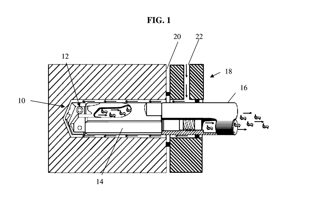
[0021]Referring now to FIG. 1-9, examples of a drilling system according to the invention are set forth. An example of the drilling system is shown in context of use in a machining operation in FIG. 1. The drilling system 10 includes a drilling head 12 and an holder body 14, coupled to a tube 16. The STS drilling system of this example utilizes a sealed bushing 18 up against the face of a part 20, which induces coolant around the connected tube 16 by means of an inlet 22, and allows coolant to flow around the drilling head 12 and back through the coolant inlets in holder body 14, flushing metal chips produced during drilling down the inside of the tube 16. The STS drilling system requires a cutting fluid delivery system for providing a volume of cutting fluid at pressures of up to 1000 pounds per square inch (about 689.4 kilopascals) or more.

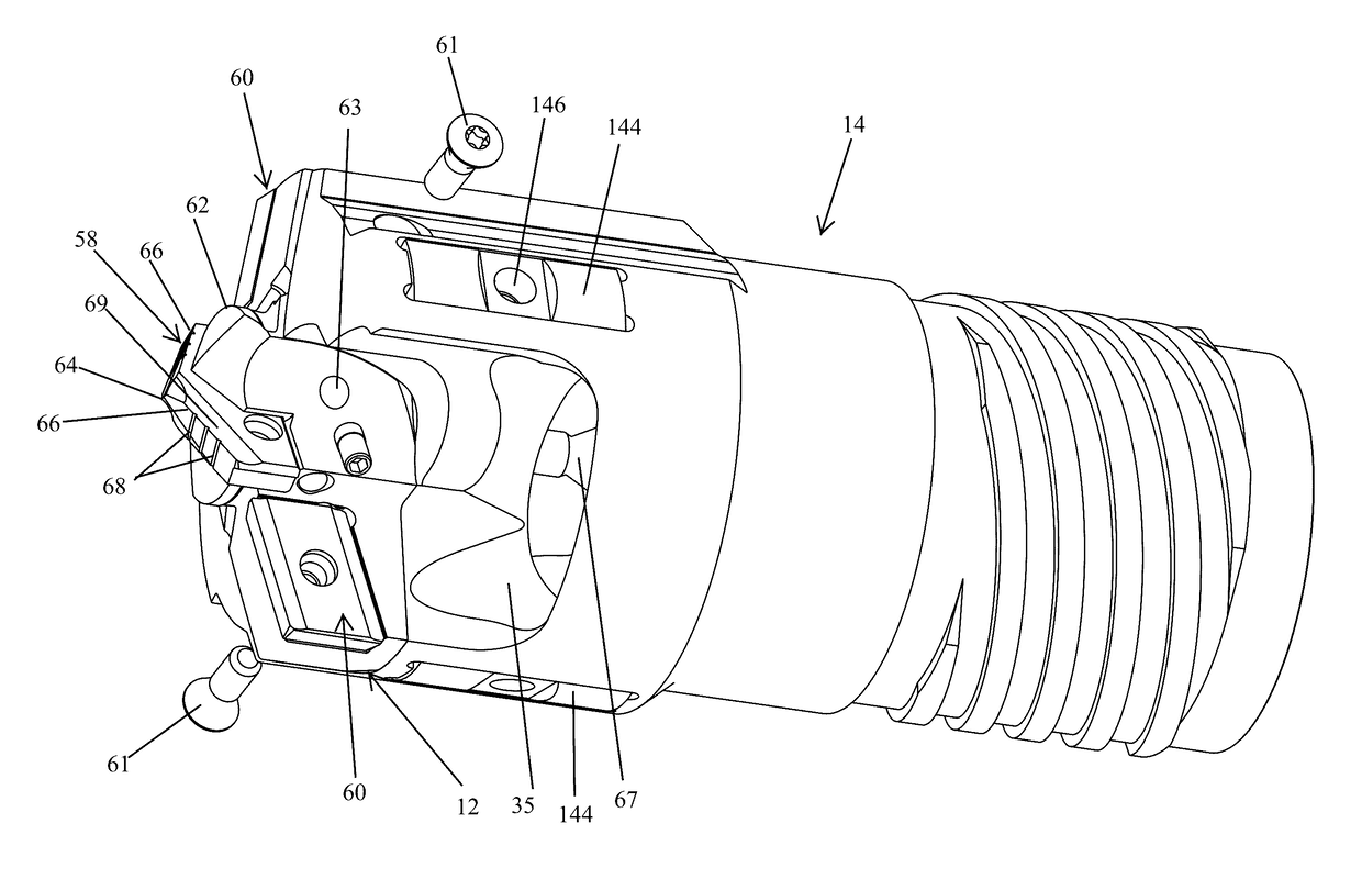
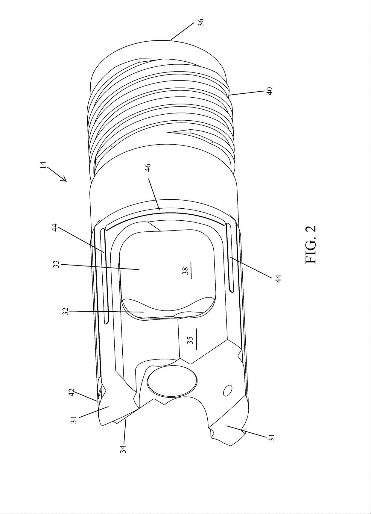
[0022]In this example, the holder body 14 may comprise a generally tubular shape having a first end, or shank end 36, and a second end 34. An e...


PUM


Abstract

A deep hole drilling system and methods provide stability and cutting performance to produce deep holes having desired straightness. The system may include a replaceable cutting head provided with a center cutting member and first and second side cutting inserts. The tool provides a major diameter with the OD cutting margins on the replaceable side inserts, as well as possibly cutting margins on the center cutting member. Adjustment mechanisms are provided to adjust the center cutting member and / side cutting inserts.

Description

CROSS REFERENCE TO RELATING APPLICATION[0001]This non-provisional application claims priority to and the benefit of U. S. Provisional Patent Application Ser. No. 62 / 221,913, filed on Sep. 22, 2015, which is incorporated herein by reference in its entirety.FIELD OF THE INVENTION[0002]The present invention relates to the field of drilling, and in particular, to deep hole drilling systems, which produce holes with a large depth to diameter ratio in an accurate and effective manner.BACKGROUND INFORMATION[0003]Certain deep hole drilling systems such as gun drills, single tube drilling systems, and double tube drilling systems are known in the art. These deep hole drilling systems may be used for drilling holes with a large depth to diameter ratio.[0004]Solid carbide tooling is disadvantageous due to the need to regrind the cutting edges when worn, requiring removal of the tool from the drilling machine. Other problems with deep hole drilling tools include instability during drilling and ...

Claims


Application Information

Patent Timeline
Patent Type & Authority Applications(United States)
IPC IPC(8): B23B51/04B23B51/00
CPCB23B51/0493B23B51/009B23B2251/54B23B2251/505B23B2250/12B23B2251/422E21B10/633B23B2251/56B23B2251/68B23B51/063B23B51/02B23B51/00B23B51/0411
Inventor BEST, PAUL W.DELUCA, SALVATORE D.DUMMERMUTH, LUCAS S.CARLISLE, DAVID J.
Owner ALLIED MASCH & ENG CORP
Why Eureka
Try Eureka