
Pressure sensor

a pressure sensor and sensor technology, applied in the field of pressure sensors, can solve the problems of reducing productivity and affecting the accuracy of the sensor, and achieve the effect of suppressing the variability of the detected pressure of the sensor due to variations in the assembly thereof and facilitating calibration of the pressure sensor

Active Publication Date: 2017-03-23
SMC CORP
View PDF15 Cites 3 Cited by
  • Summary
  • Abstract
  • Description
  • Claims
  • Application Information

AI Technical Summary

Benefits of technology

The present invention provides a pressure sensor with easy calibration. The sensor is stable and securely fixed to the body of a device. This reduces variations in pressure detection due to assembly and ensures accurate measurements. Additionally, the invention minimizes the offset voltage caused by strains, which makes calibration easier.

Problems solved by technology

However, with the aforementioned pressure sensor, due to the occurrence of variations in the constituent parts such as bodies, holders, or the like, cases occur in which the weighted and fixed position of a ceramic sensor by the body and the holder thereof is not constant, and such a position is subjected to variability.
As a result, adjustment of the offset voltage becomes complicated, which leads to a decrease in productivity.

Method used


Image

  • Pressure sensor
  • Pressure sensor
  • Pressure sensor

Examples


Embodiment Construction

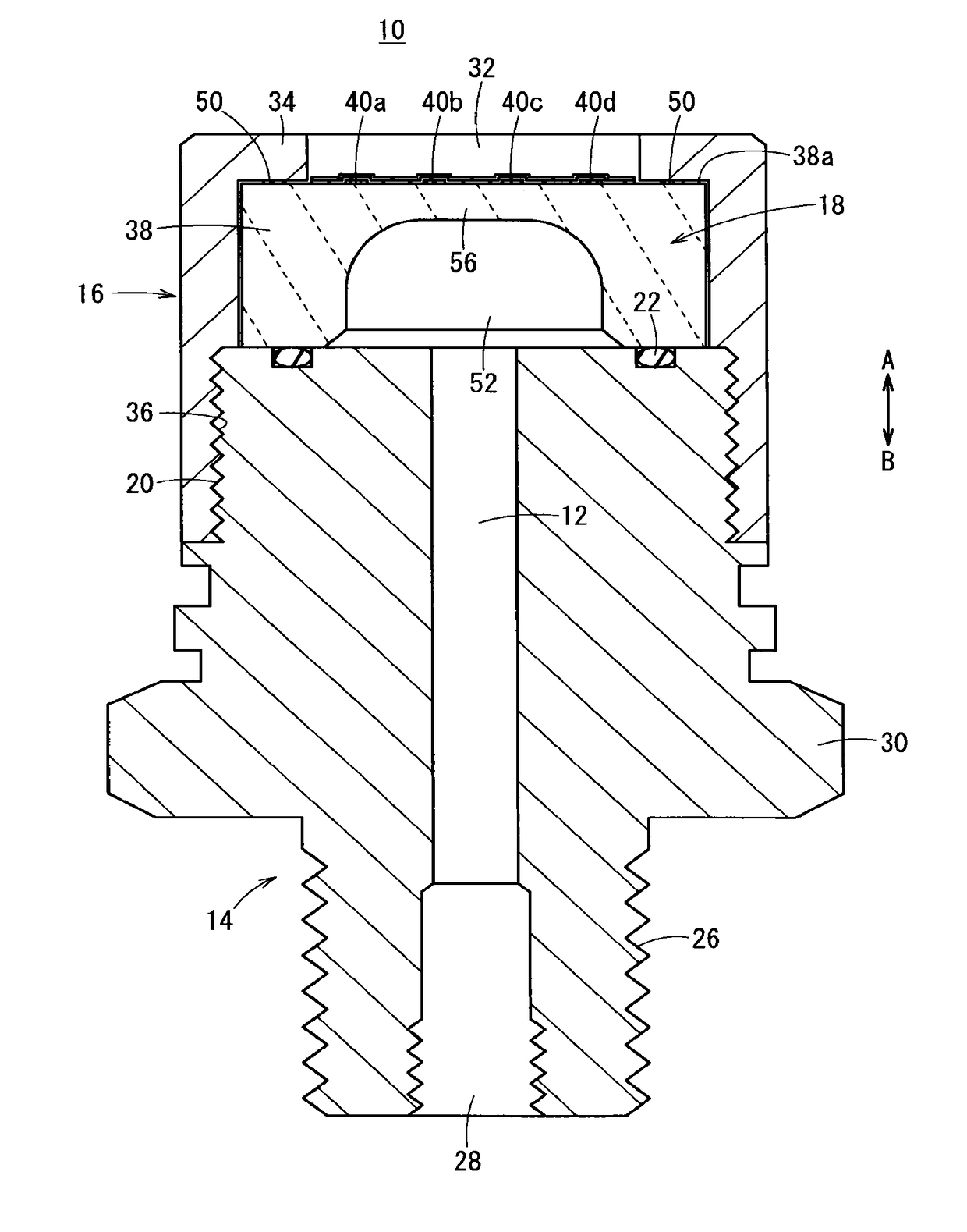
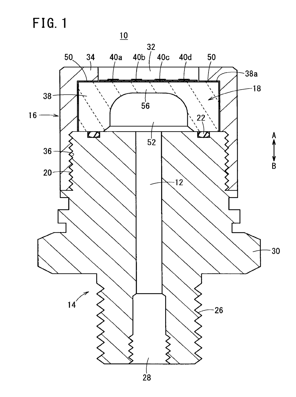
[0021]As shown in FIG. 1, a pressure sensor 10 includes a body 14 having a fluid passage 12 into which a pressure fluid is introduced, a holder 16 mounted on one end of the body 14, and a sensor 18 that is disposed in the interior of the holder 16 between the holder 16 and the body 14.

[0022]The body 14, for example, is formed from a metal material, with a first screw section 20 being disposed on an outer circumferential surface of one end thereof that is formed with a circular shape in cross section. A holder 16, which will be described later, is connected integrally with the body 14 by screw-engagement. Further, a sealing ring 22 is disposed through an annular groove on an end surface of the one end, and abuts against a lower surface of the sensor 18 described below. The sealing ring 22 may be either annular or rectangular insofar as it is of a ring shape.

[0023]Further, positioning pins 24 (see FIG. 3) are disposed on the one end of the body 14, which project at a predetermined hei...


PUM

PropertyMeasurementUnit
heightaaaaaaaaaa
pressureaaaaaaaaaa
hardnessaaaaaaaaaa

Abstract

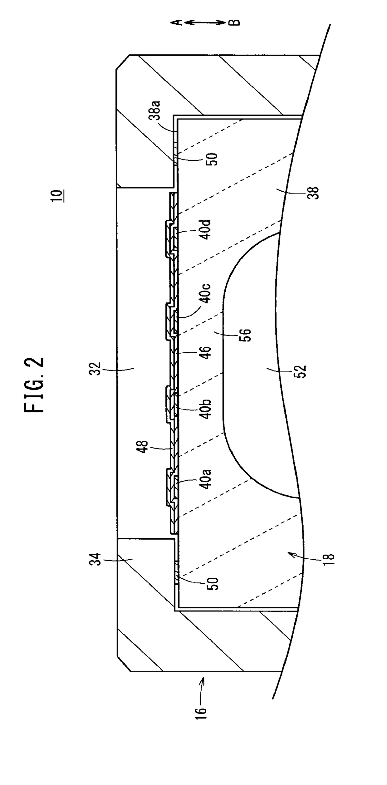
A pressure sensor is equipped with a body including a fluid passage in the interior thereof, a holder connected to one end of the body, and a ceramic sensor accommodated in the interior of the holder. Plural protrusions are disposed on an outer edge portion of an end surface of the sensor, which is pressed by the holder. In addition, when the holder is fastened with respect to the body, in a state in which a pressing portion of the holder abuts against the protrusions, a fastening force is applied in an axial direction, and the sensor is fixed.

Description

CROSS-REFERENCE TO RELATED APPLICATION[0001]This application is based upon and claims the benefit of priority from Japanese Patent Application No. 2015-185684 filed on Sep. 18, 2015, the contents of which are incorporated herein by reference.BACKGROUND OF THE INVENTION[0002]Field of the Invention[0003]The present invention relates to a pressure sensor that detects the pressure of a pressure fluid that flows inside a fluid passage.[0004]Description of the Related Art[0005]Heretofore, on a manufacturing line in which water, oil, and a chemical solution or the like are used, a pressure sensor has been used for the purpose of measuring the pressure of such fluids. Such a pressure sensor, for example, as disclosed in Japanese Laid-Open Patent Publication No. 2009-085931, is made up from a body formed in a joint-shape, a ceramic sensor accommodated in the interior of the body, and a thin film that is disposed between the sensor and a port of the body. The thin film is disposed so as to ab...

Claims


Application Information

Patent Timeline
Patent Type & Authority Applications(United States)
IPC IPC(8): G01L9/00
CPCG01L9/0051G01L19/06G01L9/0044G01L9/0055G01L9/0075G01L2009/0066G01L9/0052
Inventor SAITOH, MITSUHIROOSHIMA, YUTAYAMAGISHI, TAKESHI
Owner SMC CORP
Learn More