
Determination apparatus, determination method, and non-transitory recording medium

a technology of determination apparatus and recording medium, which is applied in the direction of instruments, transportation and packaging, image enhancement, etc., can solve problems such as the risk of erroneous determination, and achieve the effect of accurately determining the operator of a piece of equipmen

Inactive Publication Date: 2017-03-23
PANASONIC INTELLECTUAL PROPERTY MANAGEMENT CO LTD
View PDF3 Cites 5 Cited by
  • Summary
  • Abstract
  • Description
  • Claims
  • Application Information

AI Technical Summary

Benefits of technology

This patent text describes a way to determine the operator of a piece of equipment with higher accuracy. The technical effect of this invention is to provide a more accurate way to identify the operator of a machine or other piece of equipment.

Problems solved by technology

However, the apparatus disclosed in Japanese Unexamined Patent Application Publication No. 2004-67031 has a risk of erroneous determination, as the regions that are used for the determination are two equal parts into which the shot image has been simply divided and the center of gravity is the only value that is used for the determination.

Method used


Image

  • Determination apparatus, determination method, and non-transitory recording medium
  • Determination apparatus, determination method, and non-transitory recording medium
  • Determination apparatus, determination method, and non-transitory recording medium

Examples


Embodiment Construction

[0024]An embodiment of the present disclosure is described in detail below with reference to the drawings. Note, however, that, in the embodiment, components having the same functions are given the same reference numerals and, as such, are not repeatedly described.

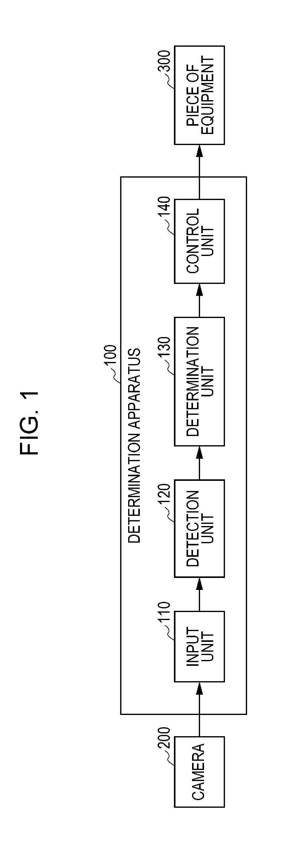
[0025]First, an example of a configuration of a determination apparatus 100 according to an embodiment of the present disclosure is described with reference to FIG. 1. FIG. 1 is a block diagram showing the example of the configuration of the determination apparatus 100 according to the embodiment of the present disclosure.

[0026]The determination apparatus 100, a camera 200, and a piece of equipment 300, which are shown in FIG. 1, are mounted on a movable body such as an automobile, a railroad vehicle, a ship, or an aircraft. The present embodiment is described by taking, as an example, a case where the determination apparatus 100, the camera 200, and the piece of equipment 300 are mounted on an automobile.

[0027]An example ...


PUM


Abstract

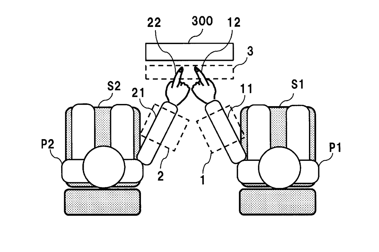
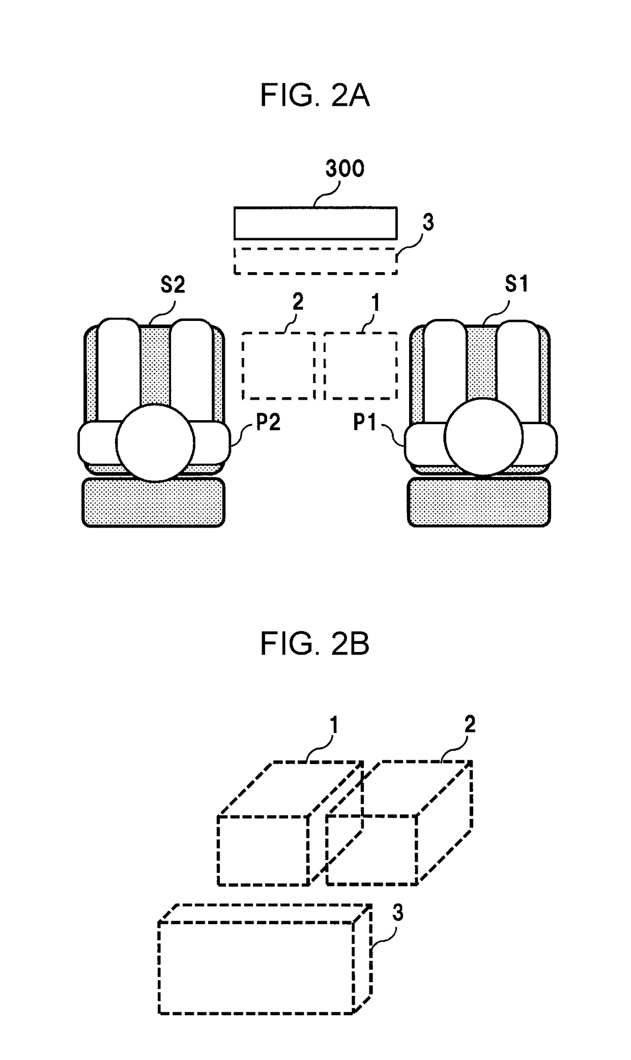
A determination apparatus includes: an receiver receives a distance image including a first region located between a first position and a second position, a second region located between the first position and the second position and located closer to the second position than the first region, a third region set within a predetermined area from an operation unit of a piece of equipment installed in front of the first position and the second position; a detector that, on a basis of the distance image, detects a first physical object of a predetermined size or larger in at least either the first region or the second region and detects a second physical object of a predetermined size or larger in the third region; and a determiner, when, in a case where the first physical object and the second physical object have been detected, the first physical object is included in the first region, determines that an operator of the piece of equipment is present in the first position or, when, in a case where the first physical object and the second physical object have been detected, the first physical object is included in the second region, determines that an operator of the piece of equipment is present in the second position.

Description

BACKGROUND[0001]1. Technical Field[0002]The present disclosure relates to a determination apparatus, a determination method, and a non-transitory recording medium.[0003]2. Description of the Related Art[0004]There has recently been known a technology for determining a person who operates a predetermined piece of equipment.[0005]For example, Japanese Unexamined Patent Application Publication No. 2004-67031 discloses an apparatus that extracts the center of gravity of a hand of an operator from a shot image and determines the operator according to whether the center of gravity is located in a left-side region or a right-side region with respect to a reference line set in the image.[0006]However, the apparatus disclosed in Japanese Unexamined Patent Application Publication No. 2004-67031 has a risk of erroneous determination, as the regions that are used for the determination are two equal parts into which the shot image has been simply divided and the center of gravity is the only val...

Claims


Application Information

Patent Timeline
Patent Type & Authority Applications(United States)
IPC IPC(8): G06K9/00B60N2/00
CPCG06K9/00838B60N2/002G06K9/00375G06F3/011G06T2207/10012G06V40/107G06V20/597B60N2/0028B60N2220/20B60N2230/20B60N2230/10G06V40/28G06V20/59G06V20/593
Inventor ARATA, KOJI
Owner PANASONIC INTELLECTUAL PROPERTY MANAGEMENT CO LTD
Learn More