OLED light emitting device and display device

Active Publication Date: 2017-03-23
TCL CHINA STAR OPTOELECTRONICS TECH CO LTD
View PDF0 Cites 0 Cited by
  • Summary
  • Abstract
  • Description
  • Claims
  • Application Information

AI Technical Summary

Benefits of technology

[0028]The beneficial effects of the present invention include: in the OLED light emitting device and the display device of the present invention, the first contact surface of the first material layer and the second contact surface of the second material layer are disposed on the substrate; the longitudinal section of the first contact surface and that of the second contact surface have sawtooth portions fitted with each other;

Problems solved by technology

However, most of the light A1 cannot output an emitting surface of the OLED light emitting device and emit to a side of the emitting surface due to the influence of the reflection and the refraction between the glass substrate 10 and the surface layer of the air area, so that a ratio of the light outputted from the emittin

Method used


Image

  • OLED light emitting device and display device
  • OLED light emitting device and display device
  • OLED light emitting device and display device

Examples


Embodiment Construction

[0033]In order to solve the technical problem by the present invention, technical solutions and beneficial effects will be more apparent below in conjunction with the accompanying drawings and embodiments of the present invention will be described in further detail. It should be understood that the specific embodiments described herein are merely for explaining the present invention and are not intended to limit the present invention.

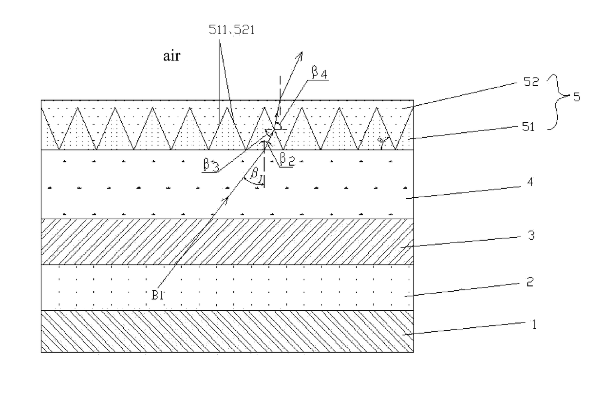
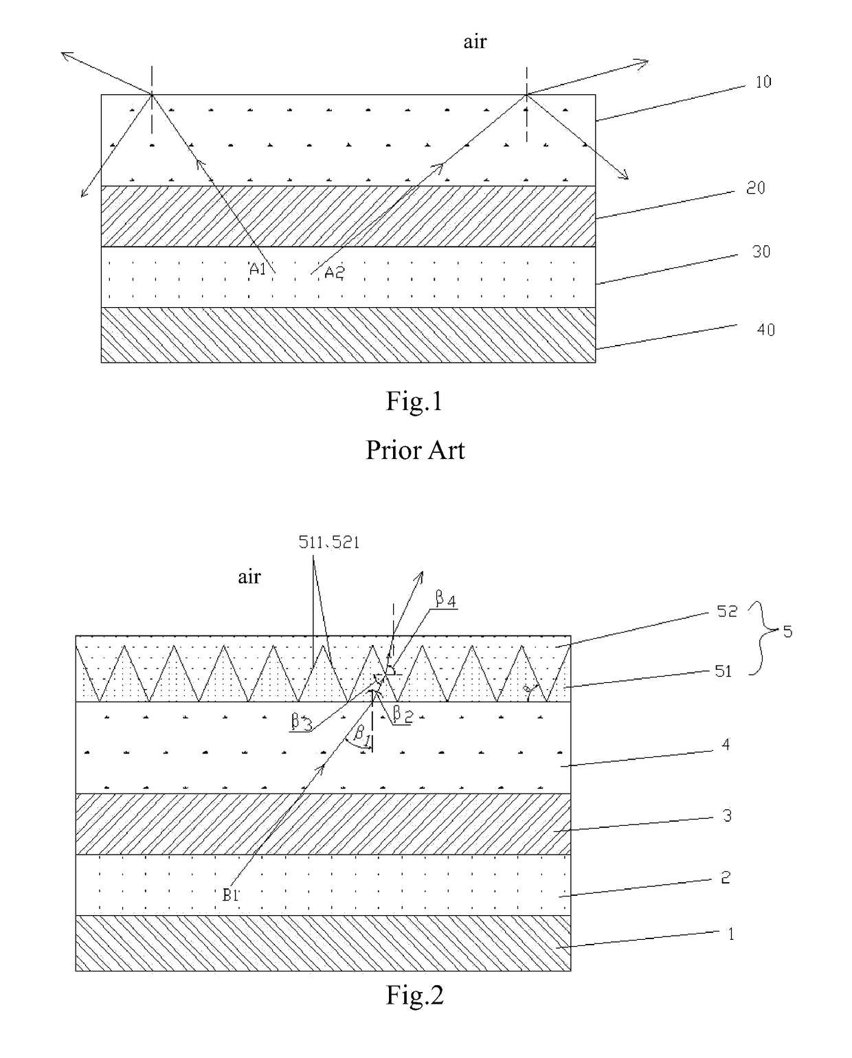
[0034]Refer to FIG. 2, the present invention provides an OLED light emitting device to a first embodiment which comprises a cathode 1, a light-emitting layer 2, an anode 3, a substrate 4, and a light extraction layer 5; wherein the light-emitting layer 2 is located between the cathode 1 and the anode 3; the substrate 4 is located between the anode 3 and the light extraction layer 5; a top surface and a bottom surface of the light extraction layer 5 are flat surfaces; the light extraction layer 5 at least includes a first material layer 51 and a second m...


PUM

PropertyMeasurementUnit
Refractionaaaaaaaaaa

Abstract

An OLED light emitting device and a display device are provided. The OLED light emitting device has a cathode, a light-emitting layer, an anode, a substrate, and a light extraction layer; the light extraction layer at least has a first material layer and a second material layer; a first contact surface of the first material layer and a second contact surface of the second material layer contact each other; a longitudinal section of the first contact surface and that of the second contact surface have sawtooth portions fitted with each other; nA>nsubstrate>nB.

Description

FIELD OF THE INVENTION[0001]The present invention relates to a technical field of displays, and in particular to an OLED light emitting device and a display device.BACKGROUND OF THE INVENTION[0002]Recently, organic light-emitting diodes have had many advantages, such as being self-luminous, having a wide view angle, fast response, high contrast, low energy consumption, being green, having a long life, being ultra-thin, and having a flexible display, which could be focused on next-generation display technology.[0003]Refer to FIG. 1, a typical OLED light emitting device comprises a glass substrate 10, an indium tin oxide (ITO) anode 20, an organic light-emitting layer 30, and a cathode 40; the organic light-emitting layer 30 is sandwiched between the ITO anode 20 and the metal cathode 40. The holes of the anode 20 and the electrons of the cathode 40 are combined in the organic light-emitting layer 30 by at applying a voltage, a light A1 could be generated by stimulating the organic ma...

Claims


Application Information

Patent Timeline
IPC IPC(8): H01L51/52H01L51/00
CPCH01L51/5275H01L51/5221H01L51/5206H01L51/0035H10K50/85H10K71/10H10K71/211H10K85/111H10K50/813H10K50/81H10K50/82H10K50/854H10K50/858H10K2101/80H10K71/00
Inventor XU, CHAO
Owner TCL CHINA STAR OPTOELECTRONICS TECH CO LTD
Why Eureka
Try Eureka