Electric power generation operation point control circuit device and multi-stage electric power generation operation point control circuit device

a technology of operation point control circuit and electric power generation, which is applied in the direction of electrical equipment, single network parallel feeding arrangement, ac network circuit arrangement, etc., can solve the problems of electric power loss as well, and achieve the effect of reducing losses and reducing losses

Inactive Publication Date: 2017-03-23
TOYOTA JIDOSHA KK +1
View PDF3 Cites 5 Cited by
  • Summary
  • Abstract
  • Description
  • Claims
  • Application Information

AI Technical Summary

Benefits of technology

[0012]The disclosure provides a configuration that is capable of reducing a loss which is generated in, for example, switching means such as a semiconductor device in an electric power generation operation point control circuit device for a photovoltaic cell that has a boosting function.
[0013]In addition, the disclosure provides a configuration that allows each photovoltaic cell to per...

Problems solved by technology

In this case, the cell with a smaller electric power generation amount acts as a r...

Method used


Image

  • Electric power generation operation point control circuit device and multi-stage electric power generation operation point control circuit device
  • Electric power generation operation point control circuit device and multi-stage electric power generation operation point control circuit device
  • Electric power generation operation point control circuit device and multi-stage electric power generation operation point control circuit device

Examples


Embodiment Construction

[0032]Hereinafter, several embodiments of the disclosure will be described in detail with reference to accompanying drawings. In the drawings, the same reference numerals will be used to refer to the same regions.

[0033]Configuration Of Electric Power Generation Operation Point Control Circuit Device (Unit)

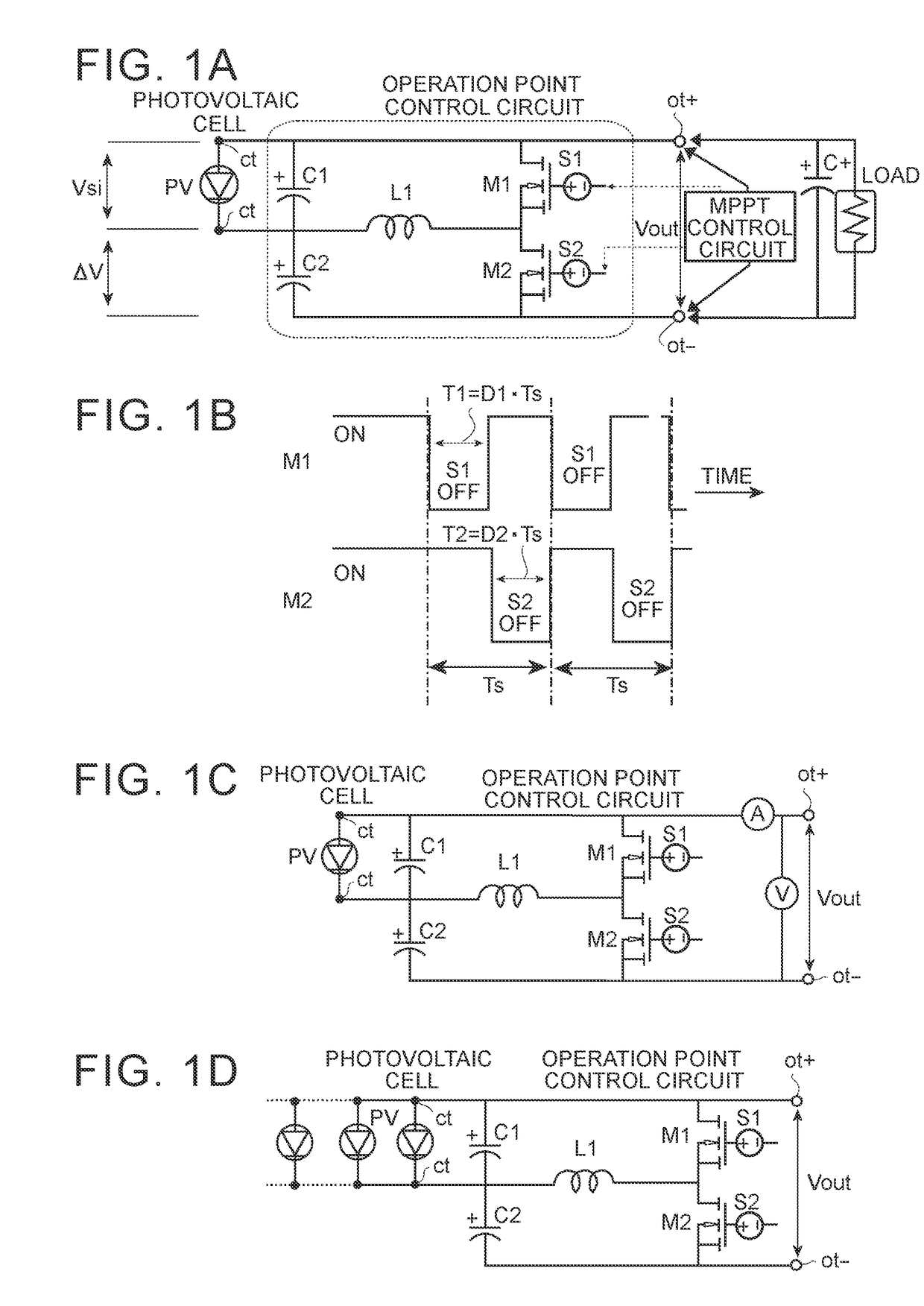
[0034]Referring to FIG. 1A, a capacitor C1 and switching means M1 are connected in parallel with respect to a photovoltaic cell PV between output terminals ot+, ot− that constitute a circuit of an electric power generation operation point control circuit device for the photovoltaic cell according to the disclosure. In addition, a capacitor C2 is added in series with respect to the capacitor C1 and switching means M2 is added with respect to the switching means M1 in the circuit that is formed by connection between the capacitor C1 and the switching means M1 via an inductor L1. It can be said that this configuration is a two-stage boosting chopper circuit configuration in which a bo...


PUM


Abstract

An electric power generation operation point control circuit device includes: a first capacitor connected in parallel to a photovoltaic cell via the pair of electrode connection terminals between the pair of output terminals; a first switching element connected in parallel to the photovoltaic cell via the pair of electrode connection terminals and the inductor between the pair of output terminals and causing a conduction state or a non-conduction state between the connected terminals; and a second capacitor connected in series to the first capacitor between a first electrode connection terminal and a first output terminal and causing the conduction state or the non-conduction state between the connected terminals.

Description

CROSS-REFERENCE TO RELATED APPLICATIONS[0001]This application claims priority to Japanese Patent Application No. 2015-184852 filed on Sep. 18, 2015, the entire contents of which are hereby incorporated by reference.BACKGROUND OF THE DISCLOSURE[0002]1. Field of the Disclosure[0003]The disclosure relates to an electric power generation operation point control circuit device for a photovoltaic cell and, more particularly, to a device that is configured to control an electric power generation voltage of a photovoltaic cell and to be capable of boosting an output voltage. In addition, the disclosure relates to a multi-stage electric power generation operation point control circuit device.[0004]2. Description of Related Art[0005]As is well known in the field of photovoltaic electric power generation technology, a photovoltaic cell has a characteristic that a current changes as an electric power generation voltage increases from 0 V as is exemplified in FIG. 6A. An optimal operation point ...

Claims


Application Information

Patent Timeline
IPC IPC(8): H02J3/38
CPCH02J3/383H02J2300/24H02J3/381Y02E10/56H02J2300/26
Inventor URABE, SHINICHISHIMIZU, TOSHIHISA
Owner TOYOTA JIDOSHA KK
Why Eureka
Try Eureka