Lateral Support Brush

a lateral support and brush technology, applied in the field of brushes and paintbrushes, can solve the problems of reducing the risk of painting moving to objects, reducing the effectiveness of counterbalance and other anti-splay features of brushes, and reducing the risk of paint moving to objects, so as to achieve greater control, less eccentric load, and optimized balance

Active Publication Date: 2017-03-30
SOLOFF BRANDON
View PDF4 Cites 7 Cited by
  • Summary
  • Abstract
  • Description
  • Claims
  • Application Information

AI Technical Summary

Benefits of technology

[0011]The brush provides an optimized balance by comprising a counterweight applied to the end of the brush which is opposite the end comprising the tuft of bristles, supporting a rearwardly-shifted balance or equilibrium point. The rearwardly shifted equilibrium point offers greater control to a painter having a regular preference of a grip in which the brush is held towards the back. The hand of such a painter that prefers a more rearward balance therefore has a lessened eccentric load about his hand, and therefore less fatigue. In addition to the benefit of decreased fatigue, a less tired hand makes easier strokes, and degradation of control is lessened. Degradation of control is a mode of error of mishandling a brush, such as to push a brush too forcefully toward a surface to be painted. Pushing a brush too forcefully is one source of compression of the tuft of bristles that results in splay. As a result, the counterbalance compounds the effectiveness of other antisplay features of the brush. To further shift rearward the equilibrium point, it is preferred to use a dowel like handle, which has a center of gravity further rearward than a handle which is tapered towards the front of the brush. Tapered handles are typical of the field of art, and the best mode of the present invention additionally differs from the prior art in this regard, by having a non-tapered handle.
[0012]The brush also provides greater lifetime resistance to splay by comprising a magnetic retaining element applied to the end of the brush which is opposite the end comprising the tuft of bristles. The magnetic element allows the brush to be retained to a magnetic surface. Where the magnetic surface is arranged such that the retainment of the brush may hold the brush at an angle optimized for drying, such as hanging invertedly or a position at which paint flows along the bristles evenly, even if not draining, such as standing vertically, the cumulative effect of drying-induced splay is minimized.
[0013]A further advantage of vertical retainment is that brushes are less likely to touch one another. Holding a brush vertically prevents transferring paint to another brush, as might happen when two brushes lay next to one another on the same surface. Also, vertical retainment decreases the risk of transferring paint to objects not meant to receive paint, such as a table or piece of clothing.”
[0014]In pursuit of reduction to practice of the present invention, it was realized that the advantages achieved with respect to a preferred mode of brushes, fine art paint brushes, such brushes having various shapes, sizes, material composition, and effect during application, were equivalently applicable to brushes which are not limited to merely fine art painting. The inventor recognizes that his invention would also have analogous use within fields of brushes wherein splay is detrimental, and contemplates embodiments having improved utility for types of brushes including at least brushes for adhesives, brushes for cosmetics, and brushes for coatings.

Problems solved by technology

Degradation of control is a mode of error of mishandling a brush, such as to push a brush too forcefully toward a surface to be painted.
Pushing a brush too forcefully is one source of compression of the tuft of bristles that results in splay.
As a result, the counterbalance compounds the effectiveness of other antisplay features of the brush.
Also, vertical retainment decreases the risk of transferring paint to objects not meant to receive paint, such as a table or piece of clothing.”

Method used


Image

  • Lateral Support Brush
  • Lateral Support Brush
  • Lateral Support Brush

Examples


Embodiment Construction

[0021]The drawings depict some useful and novel embodiments of the present invention, but do not limit the present invention to any particular displayed embodiment.

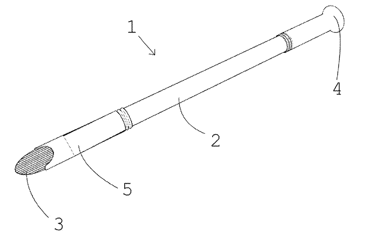
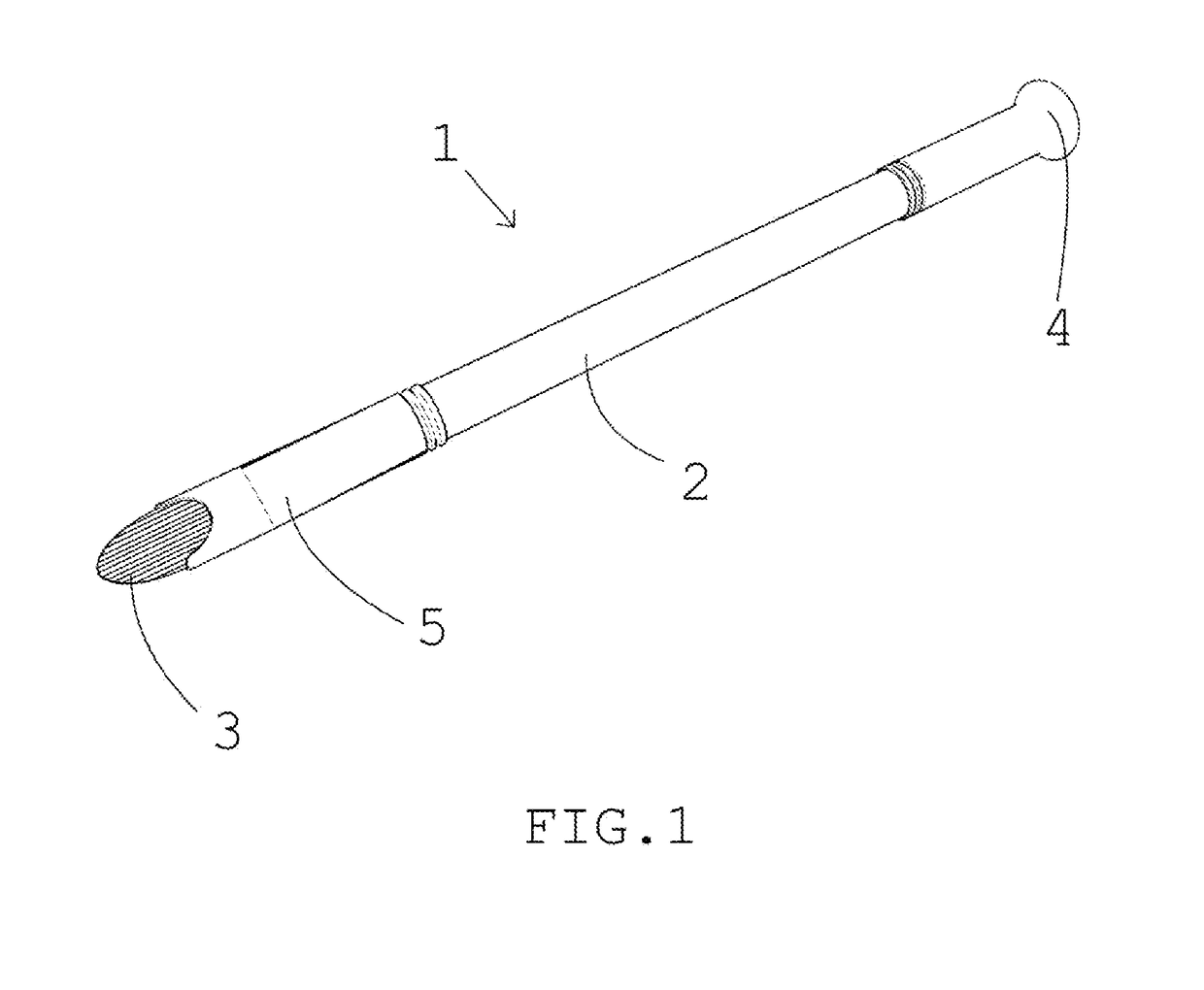
[0022]Referring now to FIG. 1, an embodiment of the present invention, a counterbalanced lateral support paintbrush (1), is shown. It has an elongate handle (2), with a tuft (3) of bristles at one end, and a counterbalancing weight (4) at the other end. A ferrule (5) connects the tuft (3) with the handle (2). In FIG. 1, the tuft (3) is a rounded tuft, an exemplary mode of tuft shape contemplated for the counterbalanced lateral support paintbrush (1).

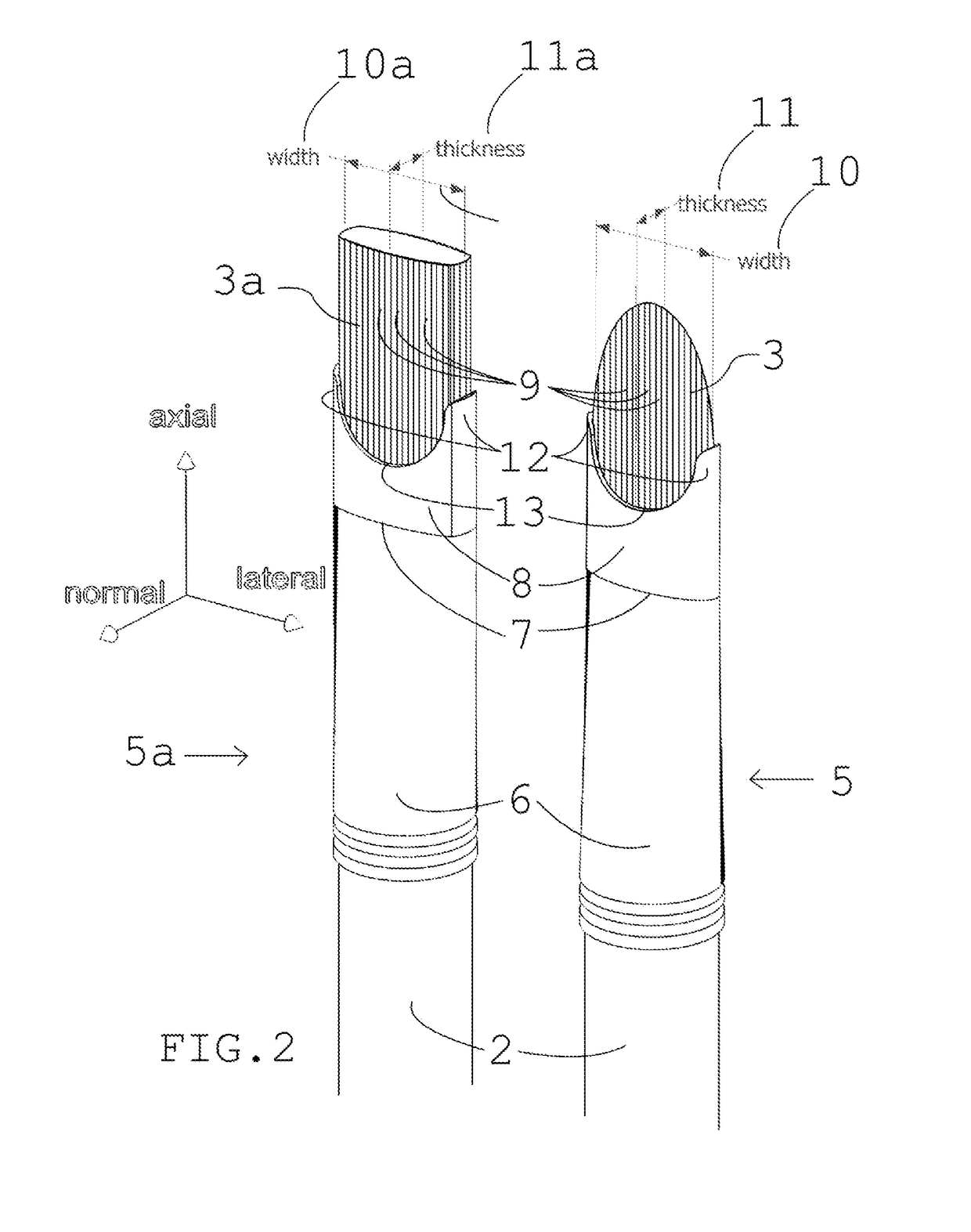
[0023]Referring now to the embodiment shown in FIG. 2, two alternative ferrules and tufts of the present invention are shown, a ferrule (5) similar to that of FIG. 1, which has a tuft (3) that is rounded in shape, and a flat-tuft ferrule (5a), which has a flat-tuft (3a). Both the ferrules (5 and 5a) are exemplary modes, but do not depict all contemplated shapes of the embodime...


PUM


Abstract

A paint brush comprises an elongate handle having a proximal end and a distal end, a tuft of bristles having properties according to at least two distinct directions, and a ferrule. The bristles are arranged substantially parallel to an axial direction and the cross section of the tuft of bristles is in a plane that has a width in a lateral direction. One end of the handle is operatively associated and is in substantially longitudinal alignment with the tuft and the ferrule is adapted to surroundingly encircle and connect said handle to said tuft of bristles so as to support the bristles against splaying in the lateral direction and limit deflection of the width.

Description

FIELD OF THE INVENTION[0001]This invention relates generally to the field of brushes, paintbrushes, and more particularly to fine art paintbrushes where precise paint application is required.BACKGROUND OF THE INVENTION[0002]Brushes, and even fine art paintbrushes, have been in use for centuries as an ordinarily understood tool for applying various liquid and powder substances for surfaces, including adhesives and coatings and paints and cosmetics. Historically, bristles are the most common method of applying paint, as a tuft comprising a multitude of bristles can deflect as a single contact region to follow the face of a surface on which to apply paint, and scribe a track having a controllably consistent thickness and width. The spaces between the bristles provide a floating volume in which paint may be retained, such that evenly laid strokes may be longer and so that successive strokes may be made, without reapplying paint to the brush as often.[0003]However, the bristles themselve...

Claims


Application Information

Patent Timeline
Patent Type & Authority Applications(United States)
IPC IPC(8): A46B9/12A46B9/02A46D99/00B25G1/10A46B5/02A46B15/00
CPCA46B9/12A46B5/02A46B9/02A46D99/00B25G1/102A46B15/0097A46B2200/205
Inventor SOLOFF, BRANDON
Owner SOLOFF BRANDON
Why Eureka
Try Eureka