Double-sided mop

a mop and double-sided technology, applied in the field of cleaning tools, can solve the problems of poor effect on floor mopping and affect the quality of cleaning, and achieve the effect of flexible operation and high quality of floor mopping

Active Publication Date: 2017-03-30
JIAXING JACKSON TRAVEL PROD CO LTD
View PDF3 Cites 4 Cited by
  • Summary
  • Abstract
  • Description
  • Claims
  • Application Information

AI Technical Summary

Benefits of technology

[0004]To solve the technical problems described above, this invention is mainly to provide a mop which is designed rationally, gives high quality of floor mopping, and offers flexible operation.
[0005]To achieve the above object, this invention provides a double-sided mop comprising a mop pole, a mop head connecting to the mop pole, and a cleaning cloth provided on the surface of mop head. The mop head comprises a first panel, a mounting plate corresponding to the first panel, a second panel that is corresponding to the first panel so as to clamp the mounting plate together with the first panel, a hinged shaft connecting to the first panel, the mounting plate, and the second panel, an elastic part connecting to the first panel and the second panel so as to make the first panel and the second panel to be normally folded or unfolded toward the mounting plate, and a universal joint that is provided on the mounting plate and connects to the mop pole and thus may run in a rotation travel so as to make the mop head rotate with respect to the mop pole. With the universal joint, the mop pole may be made to rotate all around. When the mop pole rotates tangentially around the hinged shaft, the mop pole that runs in the direction of rotation forces the first and second panels to rotate around the hinged shaft, thereby, thanks to the simplified structure and simple usage, making the mop pole freely rotate tangentially around the hinged shaft and there being no need of any slot on the first and second panels, optionally through which the mop pole passes in the stress direction. Accordingly, when the first panel or the second panel applies a force to the floor, the floor may be evenly stressed, thereby the effect of cleaning being increased.
[0006]In an embodiment, the universal joint comprises a damper hinged onto the mounting plate, and a rotation shaft that is provided on the damper and is provided for connection to the mop pole. Accordingly, the mop pole may be made to rotate around the rotation shaft. Further, the rotation shaft is vertical to the hinged shaft so that, thanks to the features of simplified structure, reasonable design, and flexible operation, the mop pole may rotate all around with respect to the mop head.
[0010]In an embodiment, the double-sided mop further comprises a counterweight block that is fixed onto the mop head and is arranged at a side of a connection where the connecting rod connects to the universal joint. With the counterweight block, when the mop is lifted relatively from the floor, the mop head automatically rotates and stops until it aligns with the mop pole, thereby facilitating water squeezing from the mop head.
[0012]Compared with the conventional technology, the technology of this invention has the advantages of simplified structure and reasonable design. Further, with the universal joint, the mop pole may be made to rotate all around. When the mop pole rotates tangentially around the hinged shaft, the connecting rod forces the first and second panels to rotate around the hinged shaft, thereby making the mop pole freely rotate tangentially around the hinged shaft. There is no need of any slot on the first and second panels for the connecting rod that is working. Accordingly, when the first panel or the second panel applies a force to the floor, the floor may be evenly stressed, thereby the effect of cleaning being increased.

Problems solved by technology

However, the slots being formed on the panel and each of the pieces of cloth, the area of slot is hollow, which brings poor effect on floor mopping due to the slots that offers effective cleaning.
Further, the panel applies a weak force to the floor, which affects the quality of cleaning.

Method used


Image

  • Double-sided mop
  • Double-sided mop
  • Double-sided mop

Examples


Embodiment Construction

[0022]The following descriptions are exemplary embodiments only, and are not intended to limit the scope, applicability or configuration of the invention in any way. Rather, the following description provides a convenient illustration for implementing exemplary embodiments of the invention. Various changes to the described embodiments may be made in the function and arrangement of the elements described without departing from the scope of the invention as set forth in the appended claims.

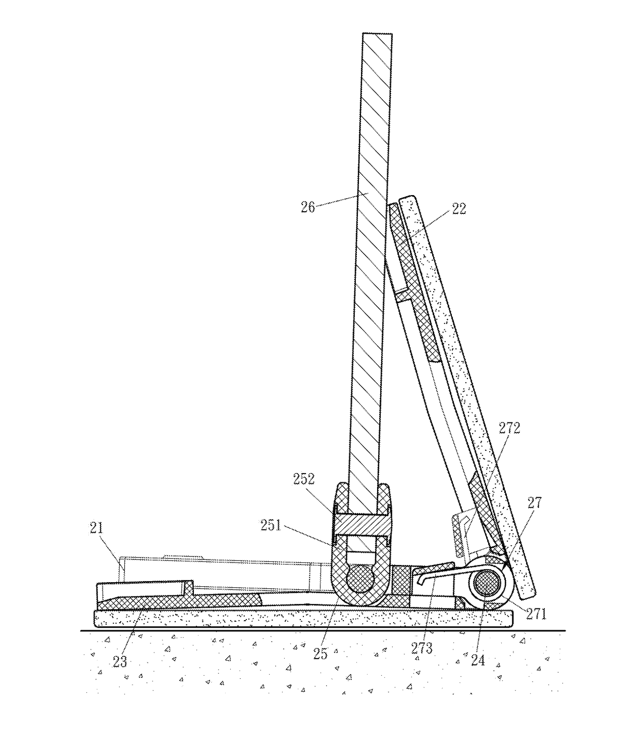
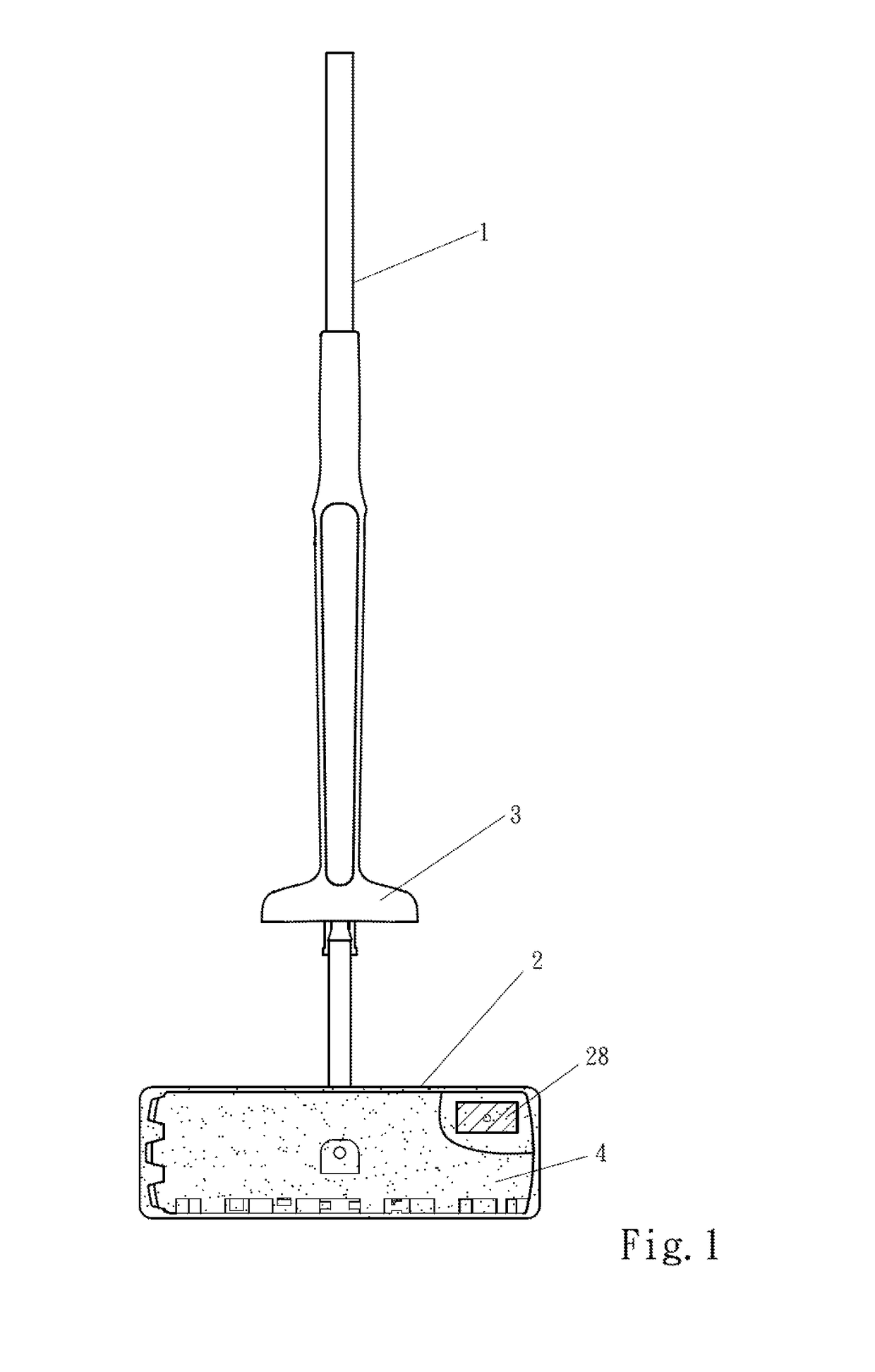
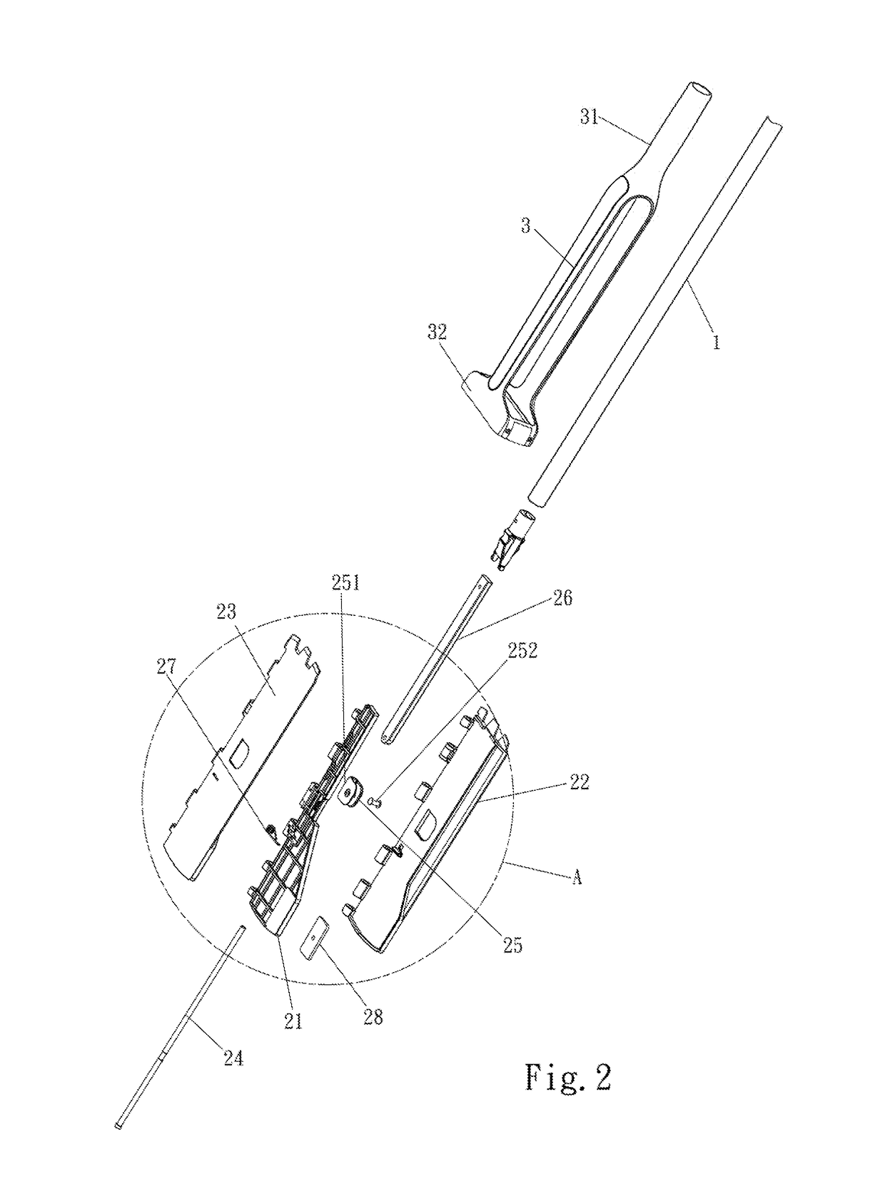
[0023]With reference to FIG. 1 through FIG. 8E, a double-sided mop according to this invention comprises a mop pole 1, a mop head 2, a water-squeezing frame 3, and a cleaning cloth 4.

[0024]In an embodiment, the cleaning cloth 4 is provided on the surface of the mop head 2. The mop head 2 comprises a first panel 22, a mounting plate 21 corresponding to the first panel 22, a second panel 23 that is corresponding to the first panel 22 so as to clamp the mounting plate 21 together with the first panel 2...


PUM


Abstract

A double-sided mop according to this invention, being provided to solve the problems of a conventional mop on poor floor mopping quality, includes a mop pole, a mop head connecting to the mop pole, and a cleaning cloth provided on the surface of mop head. The mop head includes a mounting plate, a first panel, a second panel, a hinged shaft, a universal joint, and an elastic part, in which the mounting plate is provided between the first panel and the second panel, the mounting plate is hinged and connects to the hinged shaft together with the first panel and the second panel, the elastic part applies a force to clamp the first panel and the second panel, the universal joint is installed on the mounting plate by rotation, and the mop pole connects to the universal joint.

Description

FIELD OF THE INVENTION[0001]This invention relates to a cleaning tool, particularly to a double-sided mop.BACKGROUND OF THE INVENTION[0002]A flat mop is a mop of which the head is flat so that it may completely contact the ground surface and even may go deep into dead areas of a sofa, furniture and the like. Currently, the flat mop comprises a mop head and a mop pole. The mop head comprises a panel on which a cloth is installed. To increasingly make the mop become more effective, a double-sided mop is currently implemented. The panel of the mop head of the double-sided mop has two sides on which the pieces of cloth are installed, respectively, and the mop pole is hinged between the two pieces of cloth. To make the mop pole freely rotate up and down relative to the mop head, a corresponding slot must be formed on the panel and each of the pieces of cloth, thereby making the mop pole smoothly pass through the slots. However, the slots being formed on the panel and each of the pieces o...

Claims


Application Information

Patent Timeline
Patent Type & Authority Applications(United States)
IPC IPC(8): A47L13/258B25G1/06B25G3/38A47L13/14
CPCA47L13/258B25G3/38B25G1/06A47L13/14
Inventor ZHU, XUE LINZHANG, JIU HONGLU, KAI FENG
Owner JIAXING JACKSON TRAVEL PROD CO LTD
Why Eureka
Try Eureka