Skin resurfacing device, controlling apparatus and controlling method for skin resurfacing device
Active Publication Date: 2017-03-30
LEE SEUNG HO
View PDF2 Cites 0 Cited by
Summary
Abstract
Description
Claims
Application Information
AI Technical Summary
This helps you quickly interpret patents by identifying the three key elements:
Problems solved by technology
Method used
Benefits of technology
Benefits of technology
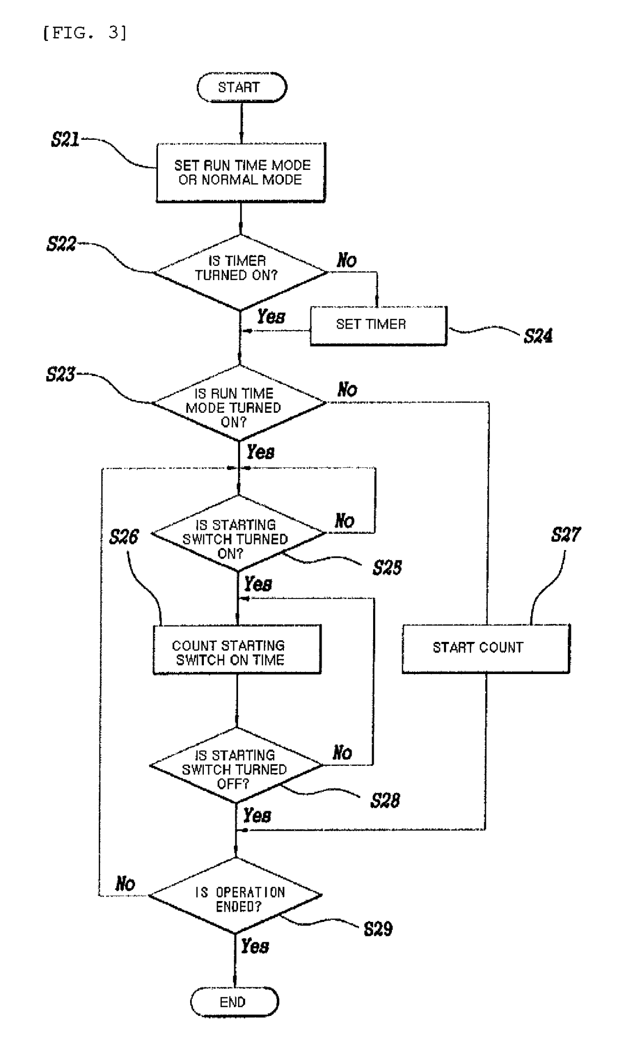
[0023]Further, the counter (not illustrated) may be controlled so as to selectively count the skin resurfacing time depending on the turn on time of the starting switch, that is, on whether to want to count the working time depending on the run time mode of cumulatively counting only the time when the skin resurfacing unit is actually operated to actually
Problems solved by technology
As a result, the above patent does not describe how the controlling apparatus corrects the irregular RPM of the motor to the regular RPM, or increases or decreases the RPM.
In the skin resurfacing to frequently drive and stop the skin resurfacing device, the operation cannot but be a very cumbersome operation.
However, a prior art for so
Method used
Image
Click on the blue label to locate the original text in one second.
Reading with bidirectional positioning of images and text.
Examples
embodiment 1
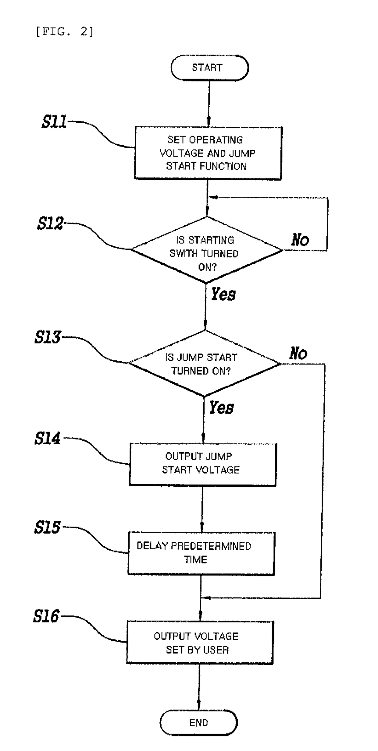
[0029]First, Embodiment 1 of the present invention will be described. Embodiment 1 relates to a jump start function. Herein, the jump start function means a function of automatically supplying, by a controlling apparatus for a skin resurfacing device, a voltage corresponding to a starting voltage to drive the skin resurfacing deice if a user performs the jump start function in a state in which a use voltage in a normal use state of the skin resurfacing device is set, and operating the skin resurfacing device at the use voltage set by the user, which is a first object of the present invention.
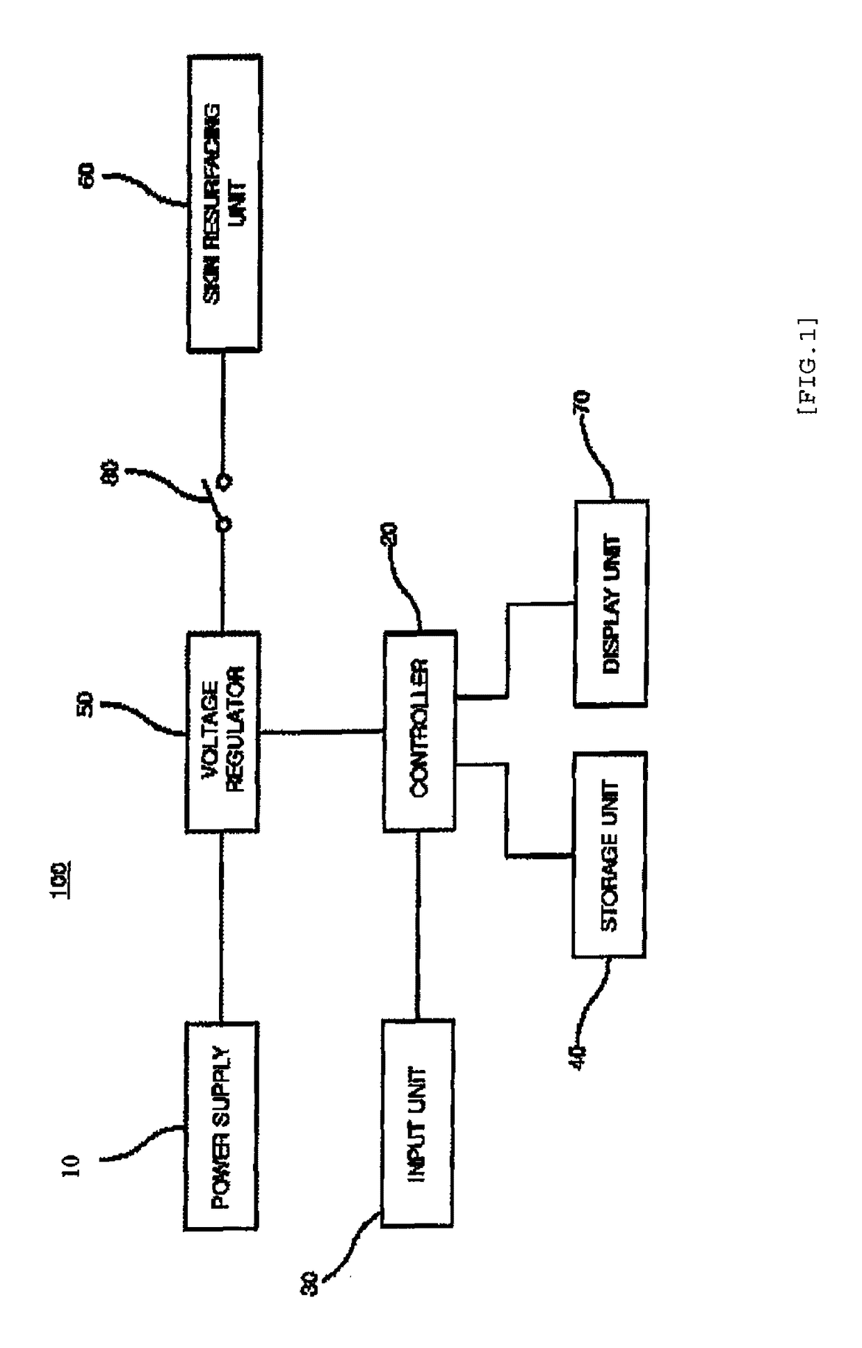
[0030]FIG. 1 is a block diagram illustrating a configuration of a skin resurfacing device 100 according to a preferable embodiment of the present invention.
[0031]As illustrated in FIG. 1, the skin resurfacing device 100 according to Embodiment 1 includes a power supply 10, a controller 20, an input unit 30, a storage unit 40, a voltage regulator 50, a skin resurfacing unit 60, and a display unit...
embodiment 2
[0052]Next, Embodiment 2 of the present invention will be described. A hardware configuration according to Embodiment 2 is basically the same as FIG. 1, and the content and operation of the control performed by the controller are different from those of Embodiment 1.
[0053]FIG. 3 is a flow chart illustrating an operation of a skin resurfacing device according to Embodiment 2 of the present invention.
[0054]First, in step S21, the user sets an operation mode of the skin resurfacing device 100 as any one of a run time mode and a normal mode. Selecting the operation mode may be performed by the input unit 30 of the skin resurfacing device 100, and the operation mode set by the user is stored in the storage unit 40. Then, the controller 20 operates the skin resurfacing device 100 depending on the operation mode stored in the storage unit 40.
[0055]Further, although not illustrated in FIG. 1, the skin resurfacing device 100 may further include a counter for counting an operation time, in wh...
PUM
Abstract
The present invention provides a controlling apparatus for a skin resurfacing device performing a surgical procedure on a human skin with a surgical needle, including: a controller 20; a voltage regulator 50 configured to regulate a voltage supplied to the skin resurfacing device from a power supply 10 according to a control of the controller; and a starting switch 80 configured to turn on/off a supply of power between the voltage regulator and the skin resurfacing device, in which the controller controls the voltage regulator so as to output a preset jump start voltage to the skin resurfacing device every time the starting switch is turned on, if a jump start function that is a function of starting the skin resurfacing device is set by a starting voltage when an operating voltage of the skin resurfacing device is lower than the starting voltage of the skin resurfacing device at the time of the surgical procedure.
Description
RELATED APPLICATIONS[0001]This application claims priority to Korean Patent Application No. 10-2015-0135177, filed on Sep. 24, 2015, in the Korean Intellectual Property Office, the entire disclosure of which is incorporated herein by reference.BACKGROUND OF THE INVENTION[0002]1. Field of the Invention[0003]The present invention relates to a skin resurfacing device capable of treating and tattooing a human skin with a surgical needle and a controlling apparatus and a controlling method for skin resurfacing device.[0004]2. Description of the Related Art[0005]Skin resurfacing has been made by various methods according to purposes such as cosmetic treatment, treatment, and tattoo. For example, the skin resurfacing for treatment purpose to remove wrinkles, pimples, or the like makes many micro holes on a human skin with a needle to inject a treatment drug into the micro holes while granulating due to autogenic power of a skin tissue damaged during the process, thereby increasing a resurf...
Claims
Application Information
Patent Timeline
Application Date:The date an application was filed.
Publication Date:The date a patent or application was officially published.
First Publication Date:The earliest publication date of a patent with the same application number.
Issue Date:Publication date of the patent grant document.
PCT Entry Date:The Entry date of PCT National Phase.
Estimated Expiry Date:The statutory expiry date of a patent right according to the Patent Law, and it is the longest term of protection that the patent right can achieve without the termination of the patent right due to other reasons(Term extension factor has been taken into account ).
Invalid Date:Actual expiry date is based on effective date or publication date of legal transaction data of invalid patent.
