Cutting apparatus and printing apparatus

a cutting machine and printing machine technology, applied in the direction of printing machine, metal working machine, other printing machine, etc., can solve the problems of difficult for users to accurately position the output rotating shaft and the input rotating shaft, and the cutter machine cannot be efficiently attached, so as to achieve high work efficiency

Active Publication Date: 2017-03-30
CANON KK
View PDF43 Cites 9 Cited by
  • Summary
  • Abstract
  • Description
  • Claims
  • Application Information

AI Technical Summary

Benefits of technology

[0007]The present invention provides a cutting apparatus in which a cutter unit can be attached to a carriage with high work efficiency, and a printing apparatus.

Problems solved by technology

However, when the cutter unit is attached to the carriage, it is difficult to correctly position the cutter unit by only the fitting of the output rotating shaft and the input rotating shaft that form the transmission mechanism for transmitting the driving force.
Moreover, since the output rotating shaft and the input rotating shaft are provided at fixed positions on corresponding the carriage and the cutter unit, it is difficult for a user to accurately position the output rotating shaft and the input rotating shaft and to quickly fit these rotating shafts to each other.
For this reason, the cutter unit could not be efficiently attached.

Method used


Image

  • Cutting apparatus and printing apparatus
  • Cutting apparatus and printing apparatus
  • Cutting apparatus and printing apparatus

Examples


Embodiment Construction

[0054]Embodiments of the invention will be described below with reference to the drawings.

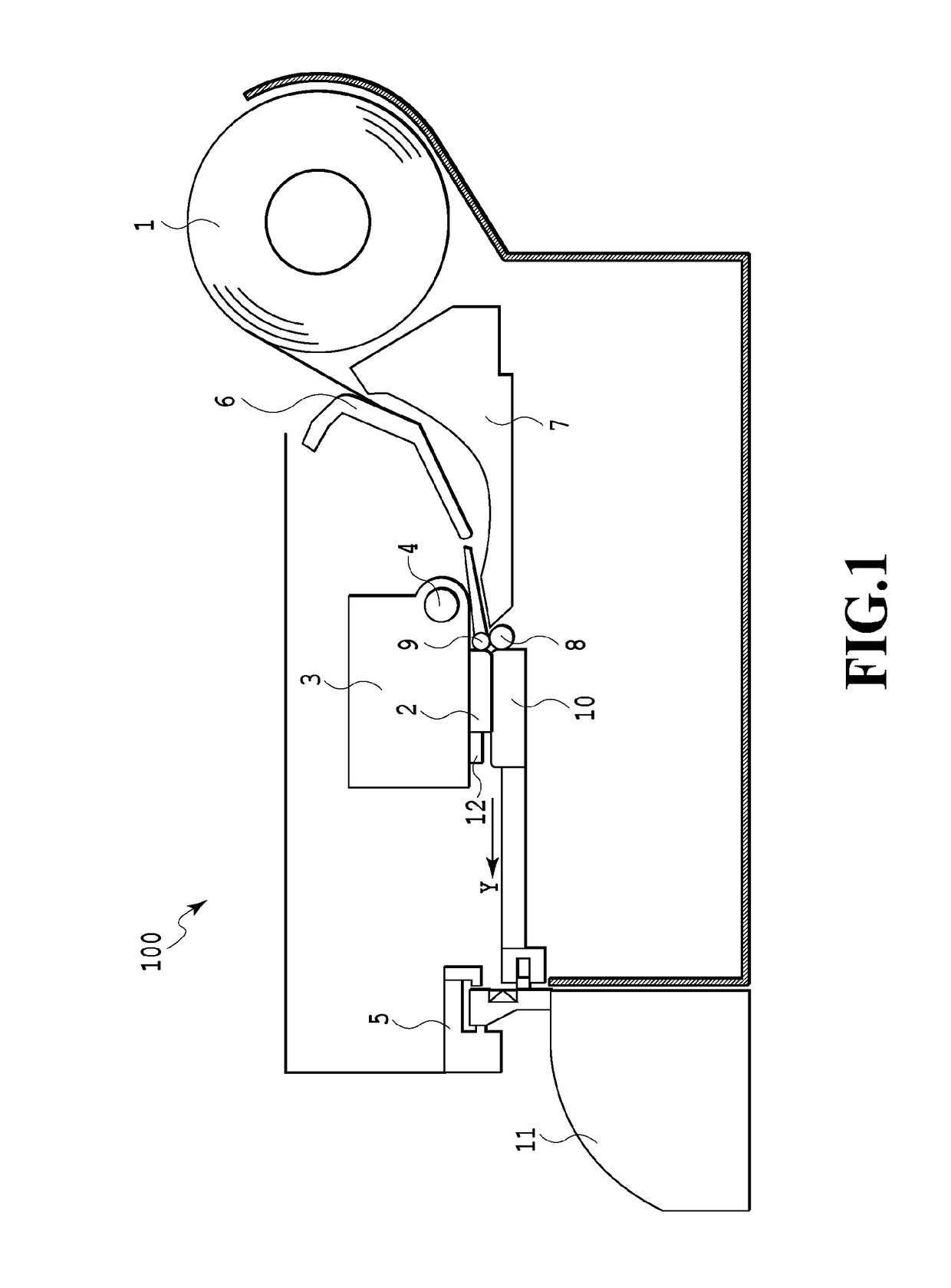
[0055]FIG. 1 is a sectional view of an ink jet printing apparatus 100 according to an embodiment of the invention. A continuous sheet 1, which is wound into a roll, is held in the printing apparatus 100, and the sheet 1 is sent through a conveying path between an upper guide 6 and a lower guide 7. The sheet 1 is held at a nip portion between a conveying roller 8 and a pinch roller 9, is conveyed in a conveying direction, which is indicated by an arrow Y, and is sent onto a platen 10 disposed at a printing position that faces a printing head 2. Images are printed on the sheet 1, which is conveyed to the printing position, with ink ejected from the printing head 2. The printing head2, a carriage 3 for printing on which the printing head 2 is mounted, and the platen 10 that is disposed so as to face the printing head 2 form an image printing unit. A carriage shaft 4 and a guide rail (not illustrat...


PUM


Abstract

A cutter unit is attached to a carriage in a predetermined direction, the carriage moving in a cutting direction of a sheet. A first set of first fitting sections and a second set of second fitting sections are provided as groups of fitting sections provided at positions, which face each other, on the carriage and the cutter unit. The first fitting sections and the second fitting sections each of which are fitted to each other in a predetermined direction. When the cutter unit is attached to the carriage, the fitting of the first fitting sections starts before the fitting of the second fitting sections.

Description

BACKGROUND OF THE INVENTION[0001]Field of the Invention[0002]The present invention relates to a cutting apparatus that can cut a sheet and a printing apparatus including the cutting apparatus.[0003]Description of the Related Art[0004]Japanese Patent Laid-Open No. 2008-30168 discloses a cutting apparatus in which a cutter unit including a rotary blade can be attached to and detached from a carriage moving in a cutting direction of a sheet, and a user can replace the rotary blade with a new rotary blade by replacing the cutter unit. The cutting apparatus is adapted so that a cutter unit-side input rotating shaft, which has a hexagonal cross-section and is connected to the rotary blade, is fitted to a hole, which has a hexagonal cross-section and is formed in a carriage-side output rotating shaft, when the cutter unit is attached to the carriage. The output rotating shaft and the input rotating shaft form a transmission mechanism that transmits a driving force used to rotate the rotary...

Claims


Application Information

Patent Timeline
Patent Type & Authority Applications(United States)
IPC IPC(8): B41J11/70B26D5/08B26D1/18
CPCB41J11/70B26D5/08B26D1/185
Inventor MASUDA, SHUICHIWAKAYAMA, NAOKINAGASHIMA, MASAKAZUANAYAMA, DAIKIKIKUCHI, TETSUOOHASHI, TAKAKAZU
Owner CANON KK
Why Eureka
Try Eureka