Automatic Shoe Cover Dispenser with Shoe Cover Cartridge

a shoe cover dispenser and automatic technology, applied in the field of automatic shoe cover dispensers, can solve the problems of inconvenient shoe cover installation, shoe cover cannot be dispensed anymore, and the production process of shoe cover packaging is relatively complicated, and achieves the effects of simple structure, low manufacturing and maintenance cost, and simple installation process of shoe cover cartridges

Active Publication Date: 2017-03-30
OTO IND WUHAN CO LTD
View PDF10 Cites 5 Cited by
  • Summary
  • Abstract
  • Description
  • Claims
  • Application Information

AI Technical Summary

Benefits of technology

[0010]Another advantage of the invention is to provide an automatic shoe cover dispenser, wherein the shoe cover cartridge is configured as a shoe cover cartridge to be loaded to the automatic shoe cover dispenser, so as to simplify the installation process of the shoe cover cartridge.
[0011]Another object of the present invention is to provide an automatic shoe cover dispenser, which is simple in structure with inexpensive manufacture and maintenance cost. In particular, no motorized device is required to dispense the shoe covers for the automatic shoe cover dispenser. In other words, the automatic shoe cover dispenser does not require any electrical power for dispensing operation.
[0012]Another object of the present invention is to provide an automatic shoe cover dispenser, wherein the shoe covers are packed together without attaching with each other. In particular, the following shoe cover is interlocked by the former shoe cover, such that after the former shoe cover is pulled and dispensed, the following shoe cover is automatically pulled by the former shoe cover to its standby position.
[0013]Another object of the present invention is to provide an automatic shoe cover dispenser, wherein each of the shoe covers is orderly pulled to enlarge its opening at the standby position.
[0014]Another object of the present invention is to provide an automatic shoe cover dispenser, which does not require to alter the original structural design of the automatic shoe cover dispenser, so as to minimize the manufacturing cost of the automatic shoe cover dispenser incorporating with the shoe cover cartridge.
[0015]Another object of the present invention is to provide an automatic shoe cover dispenser, wherein no expensive or complicated structure is required to employ in the present invention in order to achieve the above mentioned objects. Therefore, the present invention successfully provides an economic and efficient solution for providing a simple dispensing configuration for the automatic shoe cover dispenser.

Problems solved by technology

However, the major drawback of this dispensing mechanism is that the production process for packaging the shoe covers is relatively complicated since the shoe covers must be attached one-by-one.
The installation of the shoe covers is inconvenient that the shoe covers must be carefully loaded in the dispensing mechanism.
Once the connection between two sequent shoe covers is broken, the shoe covers cannot be dispensed anymore.
In other words, this shoe cover arrangement is not designed for mass production.
In addition, the shoe covers must be installed into the dispensing mechanism one-by-one so as to complicate the installation process of the shoe covers.

Method used


Image

  • Automatic Shoe Cover Dispenser with Shoe Cover Cartridge
  • Automatic Shoe Cover Dispenser with Shoe Cover Cartridge
  • Automatic Shoe Cover Dispenser with Shoe Cover Cartridge

Examples


Embodiment Construction

[0050]The following description is disclosed to enable any person skilled in the art to make and use the present invention. Preferred embodiments are provided in the following description only as examples and modifications will be apparent to those skilled in the art. The general principles defined in the following description would be applied to other embodiments, alternatives, modifications, equivalents, and applications without departing from the spirit and scope of the present invention.

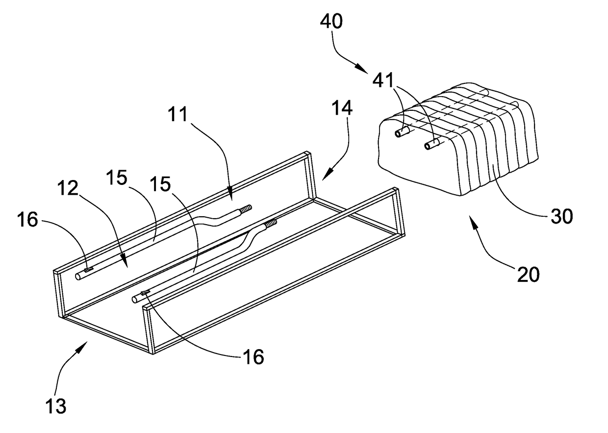
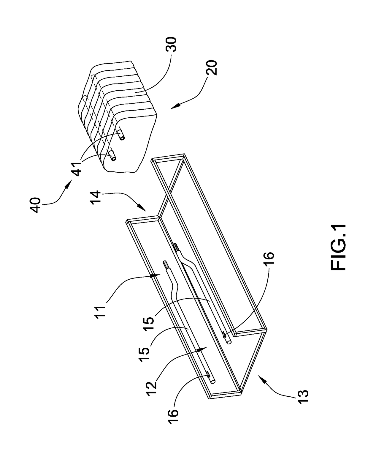
[0051]Referring to FIG. 1 of the drawings, an automatic shoe cover dispenser according to a preferred embodiment is illustrated, wherein the automatic shoe cover dispenser comprises a dispenser system 10 and a shoe cover cartridge 20.

[0052]The dispenser system 10 has a cartridge cavity 11 and a shoe disposing opening 12, and defines a dispensing direction from the cartridge cavity 11 to the shoe disposing opening 12. According to the preferred embodiment, the cartridge cavity 11 is formed at a re...


PUM


Abstract

A shoe cover cartridge includes two guiding arms and a plurality of shoe covers overlapped in a sequential manner to define a standby shoe cover and a subsequent shoe cover. Front and rear interlocking units are provided at front and rear sides of each of the shoe cover respectively and are slidably engaged with the guiding arms at a position that the front interlocking unit at the subsequent shoe cover is located in front of the rear interlocking unit at the standby shoe cover along the guiding arms. Therefore, when the standby shoe cover is pulled for dispensing, the subsequent shoe cover is pulled by the standby shoe to dispense the shoe covers in a sequential order.

Description

CROSS REFERENCE OF RELATED APPLICATION[0001]This is a Continuation-In-Part application that claims the benefit of priority under 35U.S.C.§119 to a non-provisional application having an application Ser. No. 14 / 973,737 and a filing date of Dec. 18, 2015, which is a Continuation-In-Part application that claims the benefit of priority under 35U.S.C.§119 to a non-provisional application having an application Ser. No. 14 / 515,544 and a filing date of Oct. 16, 2014.NOTICE OF COPYRIGHT[0002]A portion of the disclosure of this patent document contains material which is subject to copyright protection. The copyright owner has no objection to any reproduction by anyone of the patent disclosure, as it appears in the United States Patent and Trademark Office patent files or records, but otherwise reserves all copyright rights whatsoever.BACKGROUND OF THE PRESENT INVENTION[0003]Field of Invention[0004]The present invention relates to an automatic shoe-cover machine, and more particularly to an aut...

Claims


Application Information

Patent Timeline
Patent Type & Authority Applications(United States)
IPC IPC(8): B65D83/08A43B3/16
CPCB65D83/0894B65D83/0835A43B3/163A43D999/00A43D2200/30
Inventor XU, LIANGJIE
Owner OTO IND WUHAN CO LTD
Why Eureka
Try Eureka