Screw Pump

Inactive Publication Date: 2017-03-30
SKF LUBRICATION SYST GERMANY
View PDF4 Cites 4 Cited by
  • Summary
  • Abstract
  • Description
  • Claims
  • Application Information

AI Technical Summary

Benefits of technology

The present invention provides a screw pump that can be produced at less cost and in less time. The invention proposes a method of producing the screw pump parts, particularly the spindles, as closed-form profiles which can be more quickly and accurately than traditional methods such as grinding. This rolling process is efficient, cost-effective, and produces smooth surfaces with minimal roughness. Additionally, the invention proposes that the spindle profiles can be designed without any undercuts, which improves the efficiency of the pump. The invention also ensures a play-free intermeshing between the drive spindle and running spindle, reducing leakage losses and improving the overall performance of the screw pump.

Problems solved by technology

Since however the rolling process only allows a restricted range of profiles, rolled profiles have previously not been used for screw pumps.

Method used


Image

  • Screw Pump
  • Screw Pump
  • Screw Pump

Examples


Embodiment Construction

[0022]In the description below, the same or equivalent elements carry the same reference numerals.

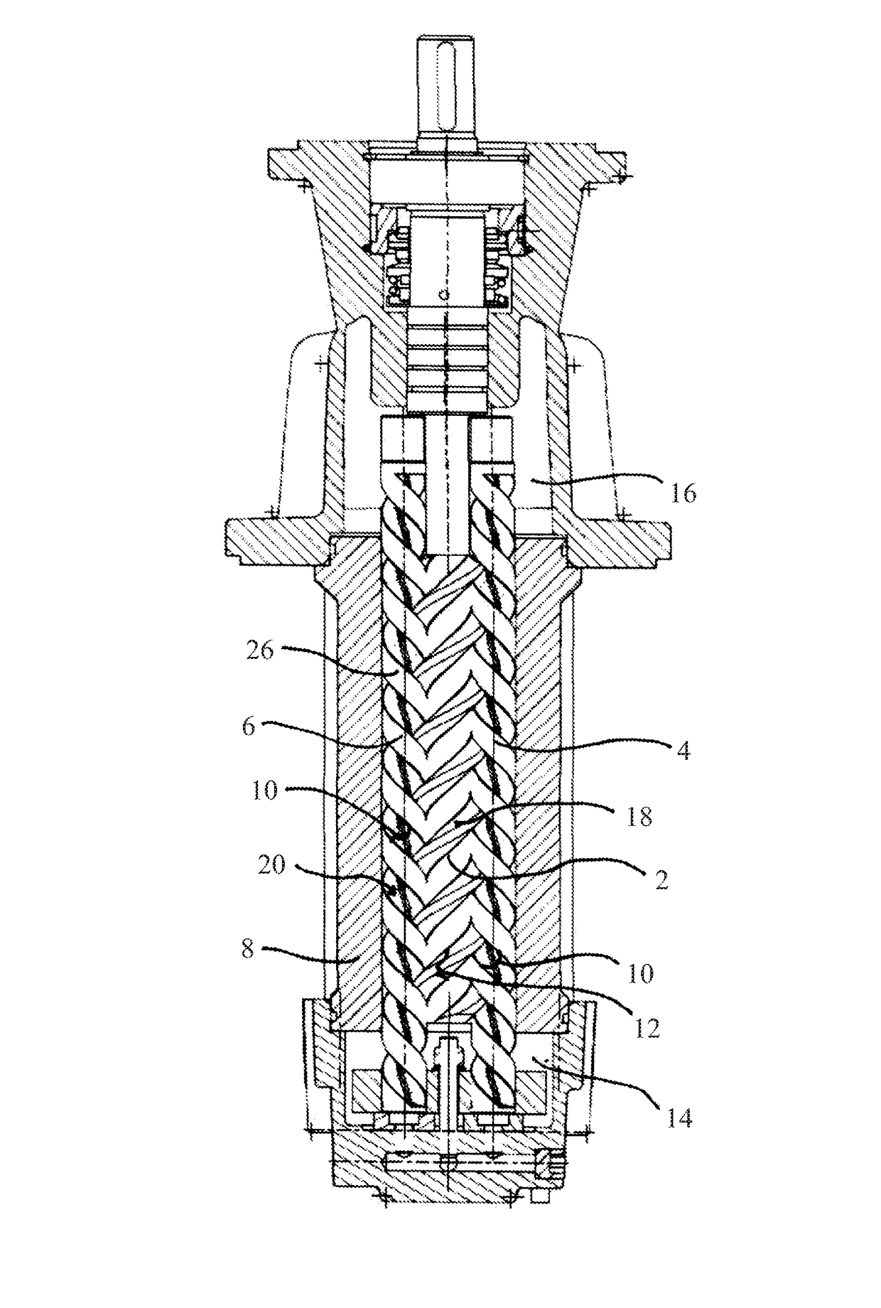
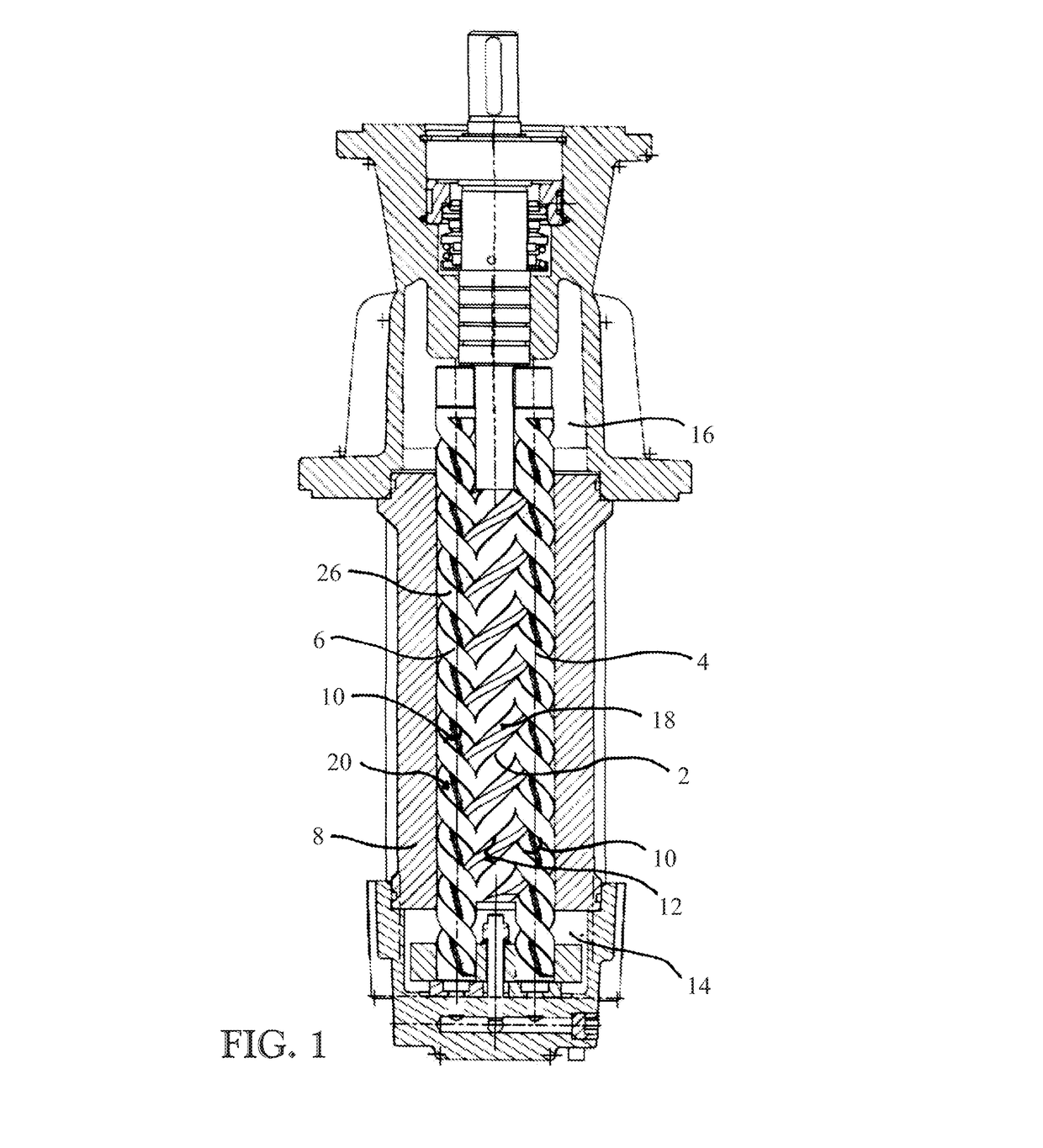
[0023]FIG. 1 shows a longitudinal section through a multiple-thread screw pump 1 with a drive spindle 2 which drives at least two running spindles 4, 6. The drive spindle 2 is rotated in the known manner via a motor. The drive spindle and the running spindles 4, 6 are in turn arranged in a housing 8, wherein the running spindles 4, 6 contact the housing 8 directly.

[0024]As further shown in FIG. 1, the drive spindle 2 and the running spindles 4, 6 intermesh so that on rotation of the drive spindle 2, the running spindles 4, 6 also rotate. Furthermore, the drive spindle 2 and the running spindles 4, 6 have drive spindle and running spindle profiles 10, 12 which are configured complementary to each other, so that on rotation of the spindles, a fluid can be “screwed” from a first chamber 14 into a second chamber 16. The flanks 18, 20 of the running spindles and drive spindle 2 are curved co...


PUM


Abstract

A screw pump for transporting a fluid, with a drive spindle having a drive spindle profile and with at least one running spindle having a running spindle profile, the running spindle engages with its running spindle profile at least partially in the drive spindle profile of the drive spindle, the drive spindle profile and / or the running spindle profile is formed as a rolled profile, and a method for producing a spindle for such a screw pump, and a method for producing a groove in such a spindle are disclosed.

Description

CROSS REFERENCE TO RELATED APPLICATIONS[0001]This application claims priority to German patent application no. 102015218679.2 filed on Sep. 29, 2015, the contents of which are fully incorporated herein by reference.FIELD OF THE INVENTION[0002]The present invention concerns a screw pump for transporting a fluid, with a drive spindle and a running spindle, a method for producing a spindle profile for such a screw pump, and a method for producing a lubricant groove in a spindle of such a screw pump.BACKGROUND OF THE INVENTION[0003]Screw pumps normally provide at least one drive spindle and a running spindle, the threads of which intermesh and roll on each other, whereby fluid can be transported from a first side of the screw pump to a second side of the screw pump.[0004]In order to guarantee such a fluid transport, the flanks of the spindles have special toothing profiles which are produced by means of material removal methods such as for example milling, sanding or lapping. As well as...

Claims


Application Information

Patent Timeline
IPC IPC(8): F04C2/16F04C18/16F04C29/02F04C15/00
CPCF04C2/16F04C15/0088F04C2240/20F04C29/02F04C2230/26F04C18/16B21K1/12F04C2/082F04C2/165F04C2240/60F04C2240/809F04C2250/20F04C2/084
Inventor SCHWAIGER, MICHAELKREUTZKAEMPER, JUERGENPOETZSCH, ARNOSCHMIDT, HOLGER
Owner SKF LUBRICATION SYST GERMANY
Why Eureka
Try Eureka