Method and apparatus for bulk microparticle sorting using a microfluidic channel

a microfluidic channel and microparticle technology, applied in the field of methods and apparatus for bulk microparticle sorting using a microfluidic channel, can solve the problems of not being able to capture single cells, aiming droplets precisely to an area less than 5 mm in diameter,

Active Publication Date: 2017-03-30
NAMOCELL INC
View PDF0 Cites 23 Cited by
  • Summary
  • Abstract
  • Description
  • Claims
  • Application Information

AI Technical Summary

Benefits of technology

[0019]Typically, the microfluidic channel including the detection region may be configured so that the microparticles pass through the detection region either single-file (when detecting and / or separating a single cells), or, as described herein, in groups of microparticles that are arranged abreast of each other, including side-by-side and above / below, approximately in a plane transverse to the direction of flow in the detection channel. For example, passing the group of microparticles may include passing multiple “layers” of cells through the flow switch at the same time for simultaneous inspection and sorting. Thus, multiple microparticles may be simultaneously illuminated, and the one or more (e.g., two, three, four, five, six) detectors configured to have a sensitivity such that if even a single microparticle in the group being concurrently or simultaneously illuminated have the desired property (e.g., florescence) then the entire group will be sorted and separated from the stream of microparticles passing through the detector region into the sample outlet flow path; other groups will instead by transmitted into a waste path (waste outlet flow path). The selected group of microparticles may then be examined either in smaller groups or as single microparticles. When a cartridge is used, either the same or a different cartridge may be used. For example, the same cartridge may re-circulate the microparticles transmitted to the sample outlet flow path back through the detection channel, but may limit the microparticles to smaller groups (e.g., by dilution, or by activating streamlining fluid paths as described below), or may direct the selected microparticles to a separate detection channel in the same cartridge. Alternatively or additionally, the microparticles may be loaded into a second cartridge in which they may be sorted individually or into smaller groups. Any of the apparatuses described herein may allow the user to select between group sorting and / or individual microparticle sorting. Toggling between group microparticle sorting and individual microparticle sorting may turn on / off streamlining fluid, and / or may change the pressure applied to the fluid in the detection region, and / or may alter the shape and / or size of the detection region and / or may change the path of selection. In some variations, group sorting vs. individual microparticle sorting may be selected based on the cartridge used.
[0033]For example, a fluidic network of the cartridge may be configured to switch as actively controlled by the sorting apparatus, so that the sorting apparatus may differentially direct fluid flowing through the cartridge (flow switch) based on the flow rate of the fluid within the cartridge. Further, these flow switches may be used in conjunction with an identification and control portion, such as an optical detection and / or imaging system, which can determine when a microparticle having predetermined properties is within a predetermined imaging region of the cartridge, so that the sorting apparatus can increase (or decrease) the flow rate of the fluid carrying the microparticle to sort the microparticle within the cartridge. As used herein, a cartridge may therefore act as a switch that sorts a material between two (or more) outputs from the cartridge based on the flow rate of material as it passes through the cartridge. In particular, the cartridges described herein may achieve differential flow sorting in conjunction with the sorting apparatus based on the differences between the resistance to flow through the outputs and different static fluid pressure at the interface between each output and a flow switch convergence region or sorting region in the cartridge.
[0036]In addition, any of the cartridges described herein may include features that prevent disruptions in the flow rate (e.g., preventing unintentional or uncontrolled changes in flow rate, such as turbulence) for fluid within the cartridge. Also, any of these systems may include a degasser to remove bubbles or to prevent bubble formation. Further, the flow paths through the flow switch may be configured to prevent or reduce turbulent flow.

Problems solved by technology

However, most microfluidic sorting devices sorts at a rate which is typically two or more orders of magnitude lower than that of conventional flow cytometer.
Therefore, it cannot be used to capture single cell.
Unfortunately, droplet sorting is typically limited to delivery of sorted individual cells to a relative large area (e.g., more than 5 mm in diameter); for areas smaller than 5 mm in diameter, the deliver accuracy becomes very low because droplets typically travel at speed more than 1 m / s and to aim the droplets precisely to an area less 5 mm in diameter (e.g., using electrostatic force) is very difficult, particularly the speed of droplet is not constant.
However, sorting individual cell into 384-well cell culture plate which is about 3 mm in diameter is not practical.
Unfortunately, such liquid dispensers cannot sort cells.
Having residue buildup within the cartridge may lead to inaccurate application of fluid flow through the cartridge channels.
Residue buildup within the channels may also result in inaccurate microparticle detection and sorting.
In addition to increased risk of contamination and decreased accuracy of sorting over time, current flow cytometry demands include processing large number of samples where washing the cartridge after each run may add up to large amount of time lost.

Method used


Image

  • Method and apparatus for bulk microparticle sorting using a microfluidic channel
  • Method and apparatus for bulk microparticle sorting using a microfluidic channel
  • Method and apparatus for bulk microparticle sorting using a microfluidic channel

Examples


Embodiment Construction

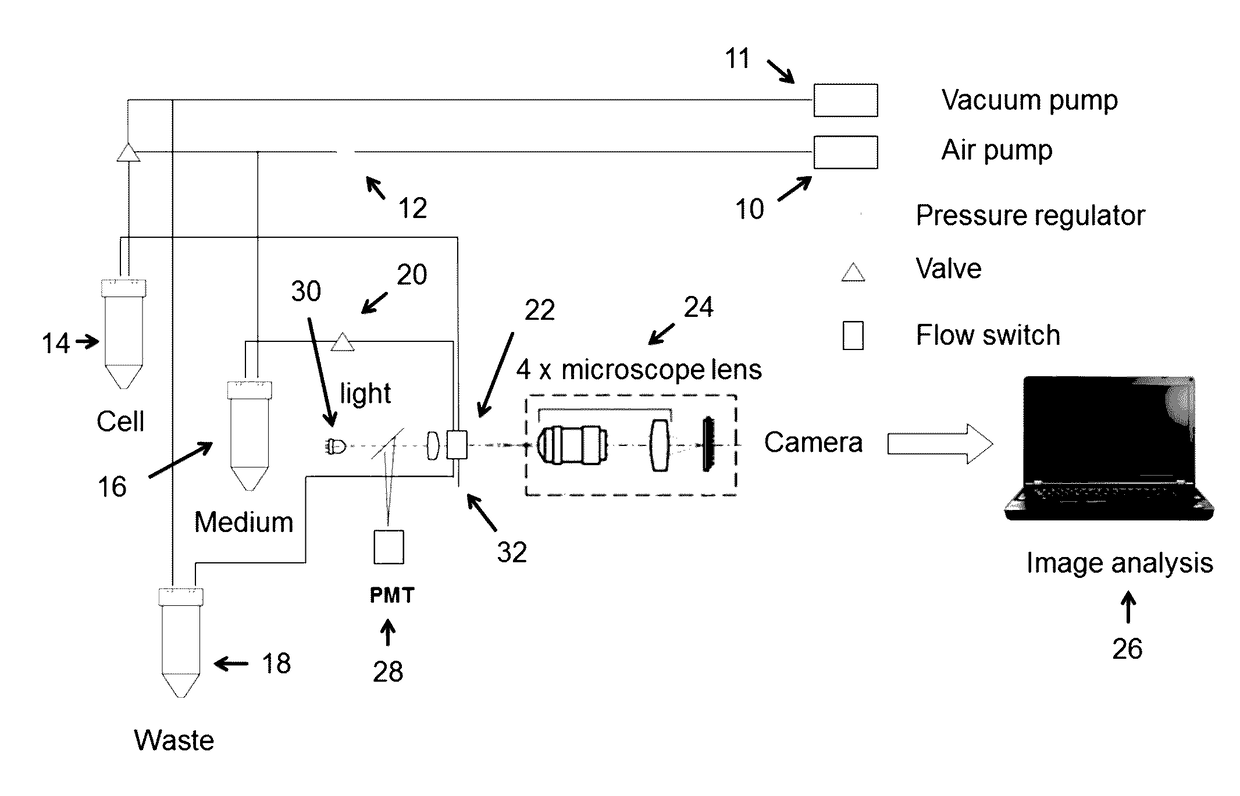
[0075]Described herein apparatuses and methods for using microfluidics to sort both groups of separate microparticles and individual microparticles. Also described herein are cartridges that may be used for sorting groups and / or individual microparticles (e.g., cells).

[0076]Although the devices and apparatuses described herein may sort based on flow rate, for example, using a flow switch, in some variations these devices and apparatuses described herein are not limited to the use of flow switches. The majority of the examples described herein are provided in the context of flow switches, but it should be understood that other sorting techniques (e.g., other microfluidic sorting techniques) may be used.

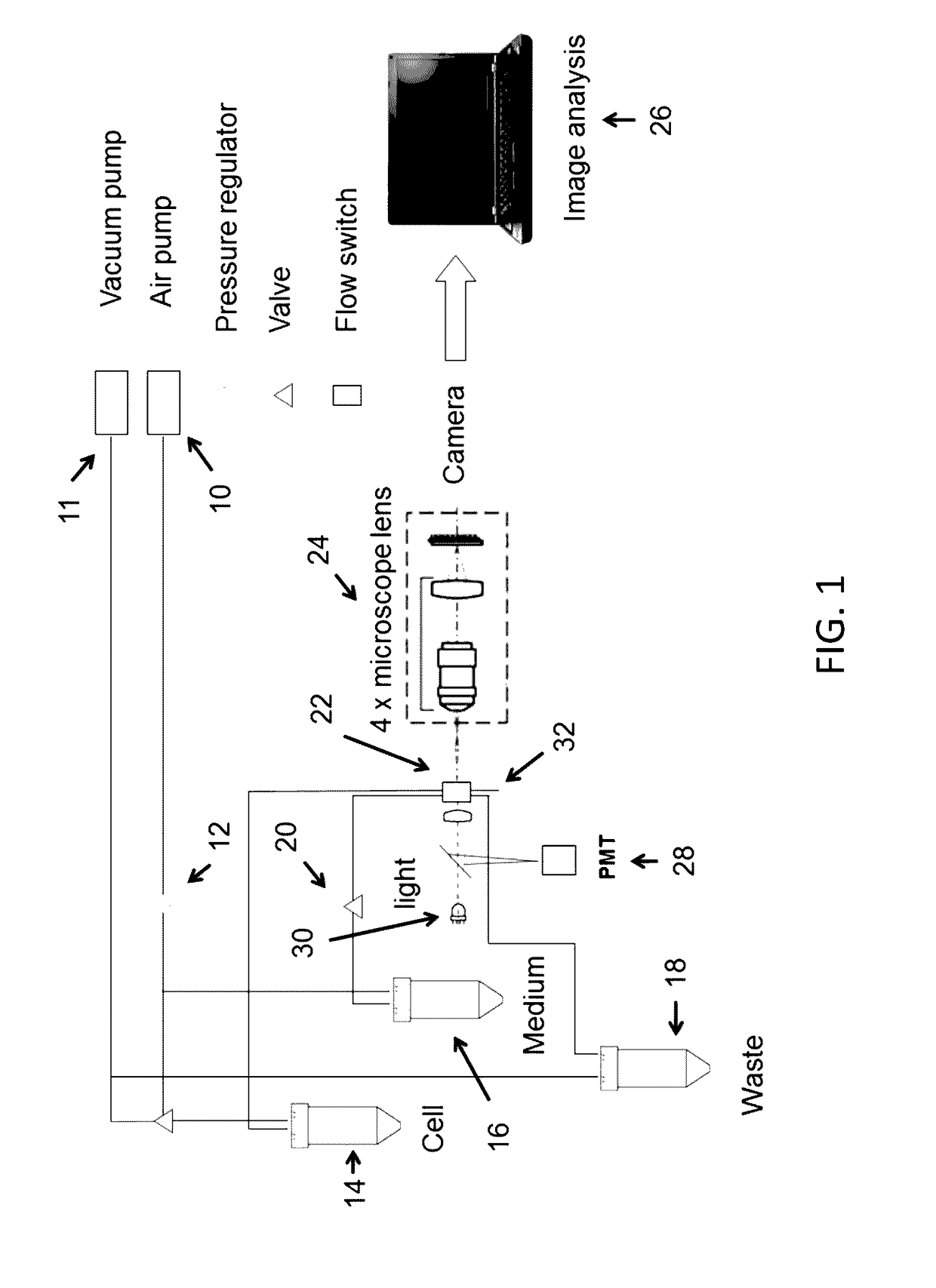
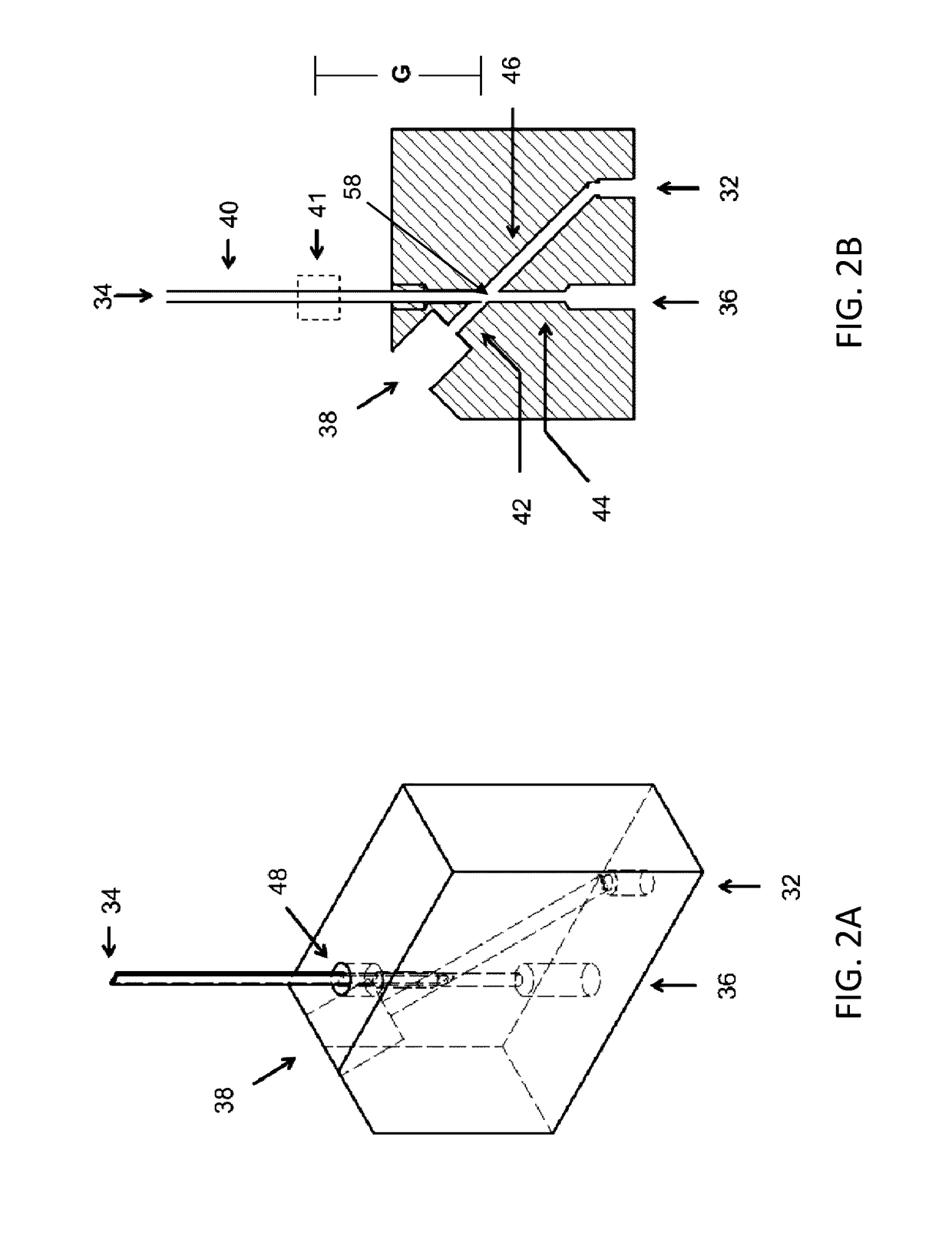
[0077]For example, the majority of the cartridges described herein are microfluidic sorting cartridges for sorting groups of microparticles and / or sorting and isolating individual microparticles, and may include a flow switch. For example, described herein are cartridges for microparti...


PUM

PropertyMeasurementUnit
diameteraaaaaaaaaa
speedaaaaaaaaaa
diameteraaaaaaaaaa

Abstract

Methods and apparatuses for sorting and isolating individual microparticles (e.g., cells) by bulk sorting groups of microparticles into groups containing one or more microparticle having a desirable characteristic (e.g., a label such as a florescent label, shape, size, etc.), and then sorting the individual microparticles with this desired characteristic individual particles.

Description

CROSS REFERENCE TO RELATED APPLICATIONS[0001]This application claims priority to U.S. Provisional Patent Application No. 62 / 323,162, filed on Apr. 15, 2016, titled “REMOVABLE MICROPARTICLE SORTER CARTRIDGE,” which is herein incorporated by reference in its entirety.[0002]This application also claims priority as a continuation-in-part of PCT Patent Application No. PCT / US2014 / 047152, filed on Jul. 18, 2014, titled “METHOD AND APPARATUS FOR PARTICLE SORTING,” which is a continuation of U.S. patent application Ser. No. 14 / 216,185, filed on Mar. 17, 2014, titled “METHOD AND APPARATUS FOR PARTICLE SORTING,” now U.S. Pat. No. 8,820,538. All of these patent applications and patents are herein incorporated by reference in their entirety.INCORPORATION BY REFERENCE[0003]All publications and patent applications mentioned in this specification are herein incorporated by reference in their entirety to the same extent as if each individual publication or patent application was specifically and ind...

Claims


Application Information

Patent Timeline
Patent Type & Authority Applications(United States)
IPC IPC(8): G01N15/14B01L3/00
CPCG01N15/1484B01L3/502753B01L3/502761B01L3/502715B01L2200/0652G01N2015/1006G01N2015/0065B01L2200/0605G01N2015/149G01N2015/1081G01N15/1459B01L3/0241B01L3/502784B01L2200/0673B01L2300/0816
Inventor LIN, JUNYU
Owner NAMOCELL INC
Why Eureka
Try Eureka