Mobile vehicle

a mobile vehicle and camera technology, applied in the field of mobile vehicles, can solve the problems of high cost, complex structure, and inability to recognize images of autonomous vehicles provided with cameras, and achieve the effects of simple configuration, reduced cost, and reduced cos

Active Publication Date: 2017-03-30
SHARP KK
View PDF15 Cites 10 Cited by
  • Summary
  • Abstract
  • Description
  • Claims
  • Application Information

AI Technical Summary

Benefits of technology

[0019]Consequently, a turning speed and shake of the imaging unit while the vehicle turns can be suppressed, whereby an image blur can be suppressed with a simple configuration without using a vibration absorption member, a vibration absorption mechanism, or the like which is specially provided. In addition, the imaging unit does not protrude outward from the electric undercarriage in the horizontal direction, which prevents the imaging unit from colliding against an obstacle while the mobile vehicle travels.

Problems solved by technology

An autonomous vehicle provided with a camera may not recognize an image because of a large image blur caused by vibration during a turn.
However, when an image blur suppression structure that is effective for all vibrations from large vibration to small vibration is applied, the structure becomes complex and takes much cost.

Method used


Image

  • Mobile vehicle
  • Mobile vehicle
  • Mobile vehicle

Examples


first embodiment

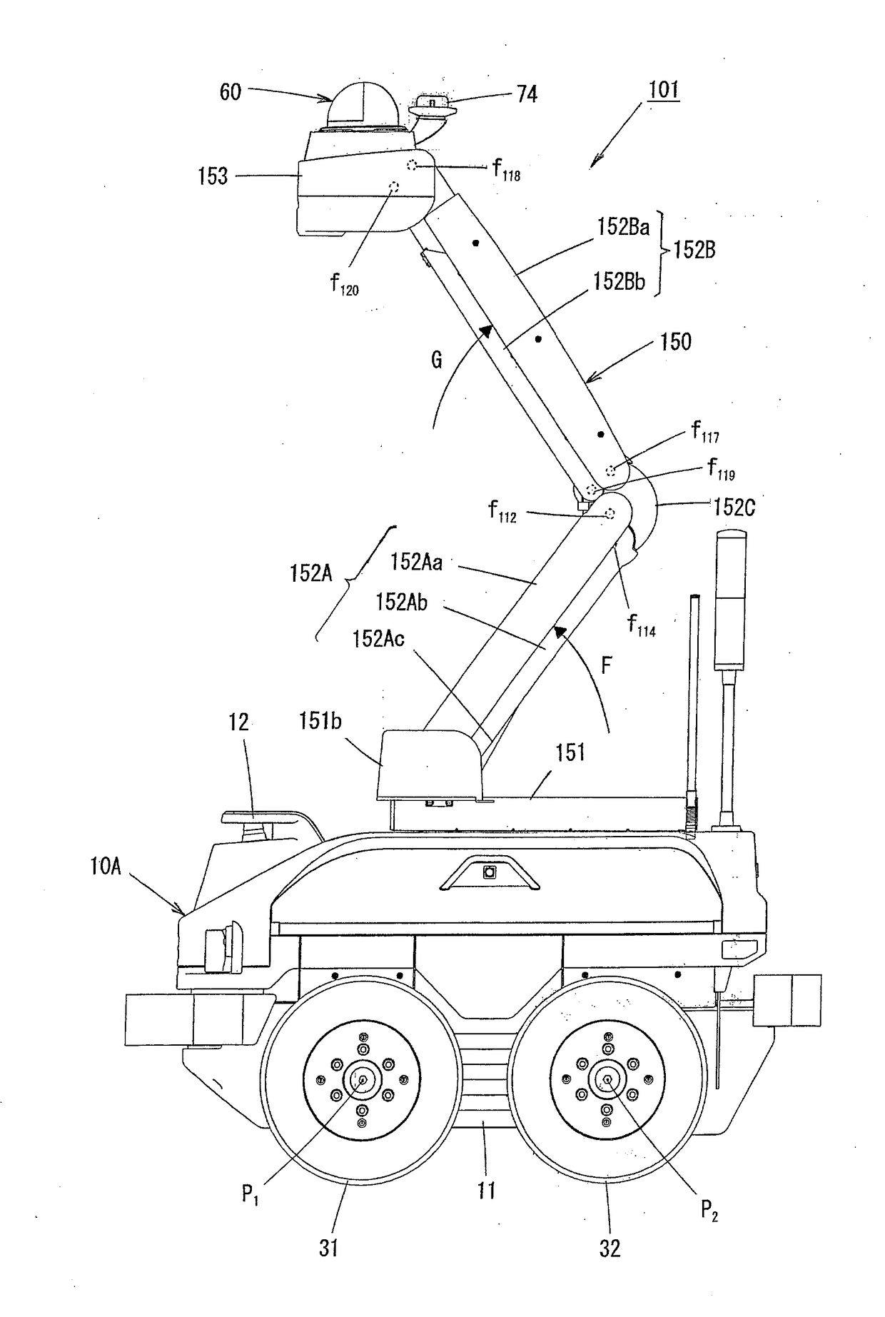
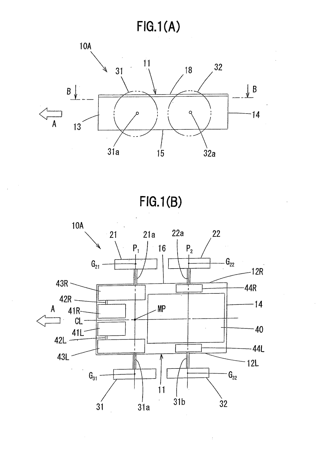
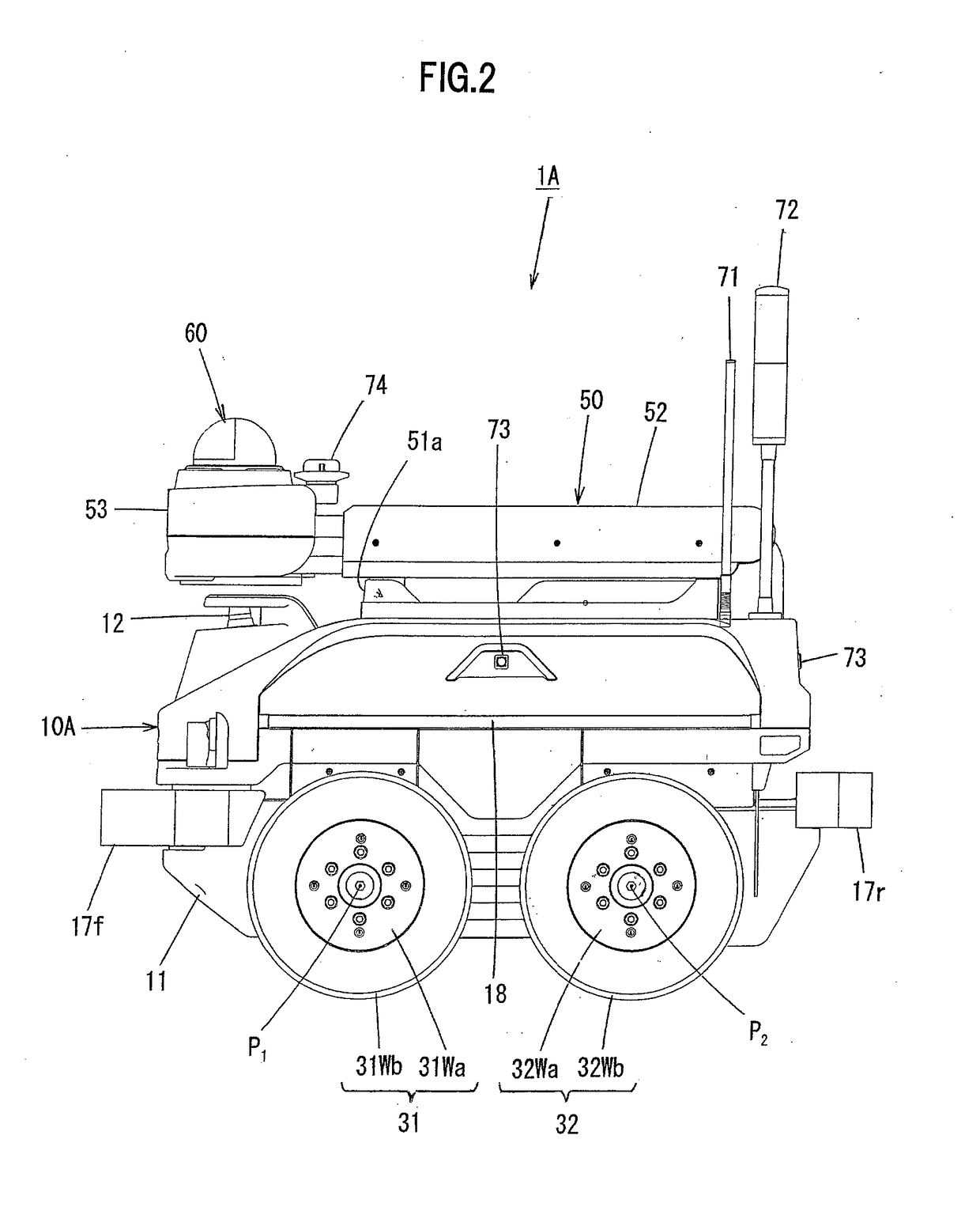
[0067]FIG. 1 is a diagram for describing a schematic configuration of an electric undercarriage of a mobile vehicle according to a first embodiment of the present invention, wherein (A) is a left side view, and (B) is a sectional view viewed from an arrow along a line B-B in (A). Also, FIG. 2 is a left side view illustrating the mobile vehicle according to the first embodiment, and FIG. 3 is a plan view of the mobile vehicle viewed from top. Further, FIG. 4 is a left side view illustrating the state in which an imaging unit of the mobile vehicle ascends according to the first embodiment, and FIG. 5 is a plan view of the mobile vehicle illustrated in FIG. 4 viewed from top.

[0068]The mobile vehicle 1A according to the first embodiment mainly includes an electric undercarriage 10A, a lift mechanism unit 50 provided on the electric undercarriage 10, and a surveillance camera 60 provided at the leading end of the lift mechanism unit 50 and serving as an imaging unit. The first embodiment...

second embodiment

[0116]FIG. 6 is a diagram for describing a schematic configuration of an electric undercarriage of a mobile vehicle according to a second embodiment of the present invention, wherein (A) is a left side view, and (B) is a sectional view viewed from an arrow along a line B-B in (A). Also, FIG. 7 is a plan view illustrating the mobile vehicle according to the second embodiment, and FIG. 8 is a plan view illustrating the state in which an imaging unit of the mobile vehicle ascends according to the second embodiment. It is to be noted that, in FIGS. 6 to 8, the components same as those in FIGS. 1 to 5 are identified by the same reference numerals.

[0117]The different point in the second embodiment from the first embodiment will mainly be described below.

[0118]The mobile vehicle 1B according to the second embodiment includes an electric undercarriage 10B which is formed by adding a right power transmission mechanism 45R that connects the front and rear wheels 21 and 22 on the right and a l...

third embodiment

[0131]FIG. 9 is a diagram for describing a schematic configuration of an electric undercarriage of a mobile vehicle according to a third embodiment of the present invention, wherein (A) is a left side view, and (B) is a sectional view viewed from an arrow along a line B-B in (A). Also, FIG. 10 is a left side view illustrating the mobile vehicle according to the third embodiment. It is to be noted that, in FIGS. 9 and 10, the components same as those in FIGS. 1 to 8 are identified by the same reference numerals.

[0132]The different point in the third embodiment from the first and second embodiments will mainly be described below.

[0133]The mobile vehicle 1B (see FIG. 6(B)) according to the second embodiment uses a wheel with tire for each of wheels 21, 22, 31, and 32.

[0134]On the other hand, a mobile vehicle 1C according to the third embodiment uses an omni wheel (registered trademark) for each of left and right rear wheels 122 and 132. In this case, it is set such that the outer surfa...


PUM


Abstract

The present invention aims to provide a mobile vehicle that can effectively suppress an image blur with a simple configuration.
The present invention provides a mobile vehicle comprising: an electric undercarriage that can travel; and an imaging unit provided on the electric undercarriage, wherein the electric undercarriage includes an undercarriage body, multiple wheels which are provided as a pair of left and right wheels on a front part of the undercarriage body and as a pair of left and right wheels on a rear part thereof, two electric motors that independently and rotationally drive the pair of left and right wheels on at least one of the front part and the rear part out of the multiple wheels, and a battery that supplies electric power to the two electric motors, the pair of left and right wheels rotationally driven by the electric motors being disposed on the same axle line, and in a plan view, the imaging unit is disposed in a circular region that is centered at a middle point on the axle line between the pair of left and right wheels rotationally driven by the electric motors and has a predetermined radius shorter than a distance between axle lines of the left and right wheels on the front and rear parts.

Description

CROSS-REFERENCE TO RELATED APPLICATIONS[0001]This application is related to Japanese Patent Application Nos. 2015-186865 filed on 24 Sep. 2015 and 2016-122738 filed on 21 Jun. 2016, whose priorities are claimed under 35 USC §119, and the disclosures of which are incorporated by reference in their entirety.BACKGROUND OF THE INVENTION[0002]1. Field of the Invention[0003]The present invention relates to a mobile vehicle, and more particularly to a mobile vehicle including an imaging unit that photographs a surveillance target.[0004]2. Description of the Background Art[0005]Recently, a mobile vehicle that autonomously moves, such as a transfer robot that transfers cargo or a surveillance robot that surveils a condition in a building, around a building, or in a predetermined site, has been used. In addition, an autonomous vehicle provided with a camera, various sensors, an arm, a boom, and the like may sometimes be used for searching sufferers in disaster areas struck by an earthquake, t...

Claims


Application Information

Patent Timeline
Patent Type & Authority Applications(United States)
IPC IPC(8): H04N5/232B60L15/20H04N7/18B60L11/18
CPCH04N5/2328H04N7/185B60L15/2036B60L11/1851B60L15/20B60L2200/40B60L2220/46Y02P90/60B60L50/66B60L50/60Y02T10/64Y02T10/70Y02T10/72H04N23/685
Inventor TOMOMASA, MASATOSHIKUNIHIRO, HISASHI
Owner SHARP KK
Why Eureka
Try Eureka