Vaporization device systems and methods

a technology of vaporizer devices and vaporizers, applied in the direction of ohmic-resistance waterproof/air-tight seals, tobacco, other medical devices, etc., can solve problems such as electrical contacts inability to work normally

Active Publication Date: 2017-04-06
JLI NAT SETTLEMENT TRUST
View PDF26 Cites 115 Cited by
  • Summary
  • Abstract
  • Description
  • Claims
  • Application Information

AI Technical Summary

Benefits of technology

[0008]In particular, described herein are cartridges that are configured for use with a vaporizer (e.g., vaporizer device) having a rechargeable power supply that includes a proximal cartridge-receiving opening. These cartridges are specifically adapted to be releasably but securely held within the cartridge-receiving opening of the vaporizer and resist disruption of the electrical contact with the controller and power supply in the vaporizer even when held by the user's mouth.
[0012]In general, applicants have found that, for cartridges having a base that fits into the rectangular opening of a vaporizer (particularly one that is between 13-14 mm deep, 4.5-5.5 mm wide, and 13-14 mm long), the it is beneficial to have a length of the base (which is generally the connection region of the base for interfacing into the rectangular opening) that is greater than 10 mm, however when the base is greater than 10 mm (e.g., greater than 11 mm, greater than 12 mm, greater than 13 mm), the stability of the cartridge and in particular the electrical contacts, may be greatly enhanced if the cartridge includes one or more (e.g., two) locking gaps near the bottom surface of the cartridge into which a complimentary detent on the vaporizer can couple to. In particular, it may be beneficial to have the first and second locking gaps within 6 mm of the bottom surface, and more specifically within 3-4 mm of the bottom surface. The first and second lateral surfaces may be separated from each other by between 13-14 mm, e.g., they may be on the short sides of a cartridge base having a rectangular cross-section (a rectangular base).

Problems solved by technology

However, a number of surprising disadvantages may result in this configuration, particular to non-cylindrical shapes.
For example, the use of a cartridge at the proximal end of the device, which is also held by the user's mouth, particularly where the cartridge is held in the vaporizer device by a friction- or a snap-fit, may result in instability in the electrical contacts, particularly with cartridges of greater than 1 cm length.

Method used


Image

  • Vaporization device systems and methods
  • Vaporization device systems and methods
  • Vaporization device systems and methods

Examples


Embodiment Construction

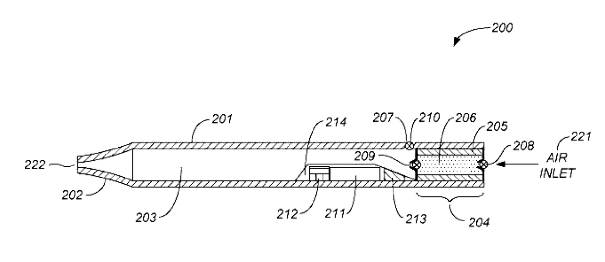
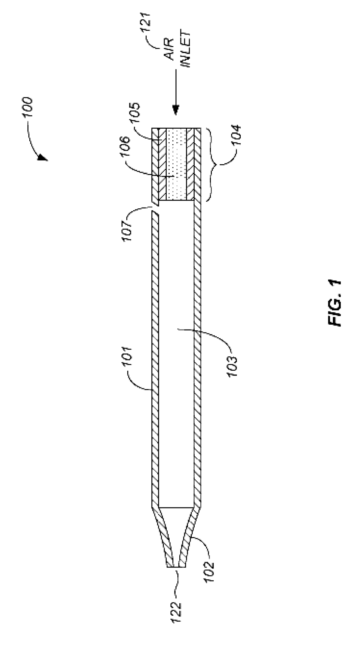
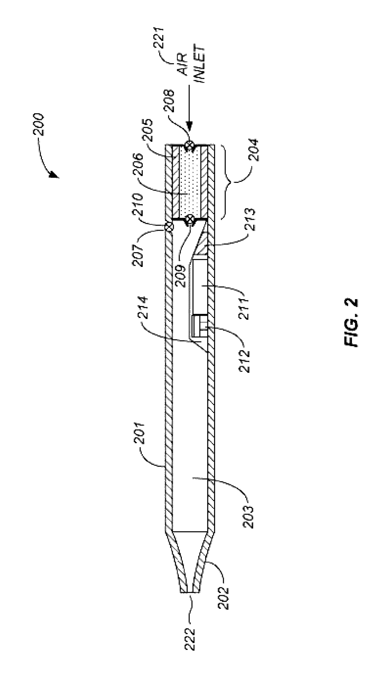
[0147]Provided herein are systems and methods for generating a vapor from a material. The vapor may be delivered for inhalation by a user. The material may be a solid, liquid, powder, solution, paste, gel, or any a material with any other physical consistency. The vapor may be delivered to the user for inhalation by a vaporization device. The vaporization device may be a handheld vaporization device. The vaporization device may be held in one hand by the user.

[0148]The vaporization device may comprise a cartridge having one or more heating elements the heating element may be a resistive heating element. The heating element may heat the material such that the temperature of the material increases. Vapor may be generated as a result of heating the material. Energy may be required to operate the heating element, the energy may be derived from a battery in electrical communication with the heating element. Alternatively a chemical reaction (e.g., combustion or other exothermic reaction)...


PUM


Abstract

Vaporization devices and methods of operating them. In particular, described herein are vaporizer cartridges for controlling the power applied to a resistive heater.

Description

CROSS REFERENCE TO RELATED APPLICATIONS[0001]This patent application claims priority as a continuation-in-part of U.S. patent application Ser. No. 15 / 053,927, filed on Feb. 25, 2016, titled “VAPORIZATION DEVICE SYSTEMS AND METHODS,” Publication No. US-2016-0174611-A1, which is a continuation-in-part of U.S. patent application Ser. No. 14 / 581,666, filed on Dec. 23, 2014 and titled “VAPORIZATION DEVICE SYSTEMS AND METHODS”, Publication No. US-2015-0208729-A1, which claims priority to U.S. Provisional Patent Application No. 61 / 920,225, filed on Dec. 23, 2013, U.S. Provisional Patent Application No. 61 / 936,593, filed on Feb. 6, 2014, and U.S. Provisional Patent Application No. 61 / 937,755, filed on Feb. 10, 2014.[0002]This patent application also claims priority to U.S. Provisional Patent Application No. 62 / 294,281, filed Feb. 11, 2016, titled “SECURELY ATTACHING CARTRIDGES FOR VAPORIZER DEVICES.” Each of these applications are herein incorporated by reference in their entirety.INCORPORA...

Claims


Application Information

Patent Timeline
Patent Type & Authority Applications(United States)
IPC IPC(8): A24F47/00H05B1/02H05B3/03A24F40/10A24F40/46
CPCA24F47/008H05B1/0244H05B3/03H05B3/04H05B3/44H05B2203/014H05B2203/016H05B2203/021H05B2203/022A61M15/06A61M2205/3653A61M2205/8206A61M11/042A24F40/46A24F40/10A24F40/51A24F40/40A24F40/57A24F40/42
Inventor MONSEES, JAMESBOWEN, ADAMHATTON, NICHOLAS JAYCHRISTENSEN, STEVENLOMELI, KEVINATKINS, ARIEL
Owner JLI NAT SETTLEMENT TRUST
Why Eureka
Try Eureka