Dispense nozzle with a dynamic liquid plug

a technology of liquid plug and nozzle, which is applied in the direction of liquid surface applicators, coatings, packaging, etc., can solve the problems of reducing the expected effect of dispense chemical on the substrate surface, affecting the expected effect of dispense chemical, and quickly degrading chemical dispensed from fabrication tools when exposed to air

Active Publication Date: 2017-04-06
TOKYO ELECTRON LTD
View PDF12 Cites 4 Cited by
  • Summary
  • Abstract
  • Description
  • Claims
  • Application Information

AI Technical Summary

Problems solved by technology

Some chemicals dispensed from fabrication tools quickly degrade when exposed to air.
The chemical degradation of the dispense chemical creates particles that may drastically reduce the expected effect of the dispense chemical on the substrate surface.
Evaporation of the dispense chemical can also change the concentration which can negatively impact the expected result of the application of the dispense chemical.
The issue with the solvent plug approach is the matter of contamination.
These particles could then contaminate the dispense chemical.
The dispense chemical is generally very expensive, so this process creates expensive waste.

Method used


Image

  • Dispense nozzle with a dynamic liquid plug
  • Dispense nozzle with a dynamic liquid plug
  • Dispense nozzle with a dynamic liquid plug

Examples


Embodiment Construction

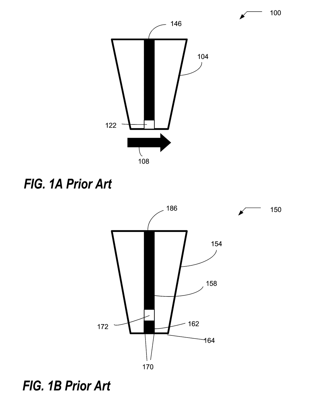
[0019]FIG. 1A is an exemplary schematic 100 of a prior art sequence of steps of operations to limit exposure of dispense chemical to air. The typical sequence of steps in the opening, using, and closing of a dispense nozzle system in prior art starts with a first step, after dispense of the dispense chemical 146, the dispense chemical 146 is sucked back into the nozzle 104. The second step creates an air pocket 122 to limit the diffusion of the evaporated vapor from the dispense chemical 146 and to limit the replacement of air 108 at the surface. In the third step, after the suck-back operation, the nozzle 104 is moved to a tray (not shown) where air 108 moves across the nozzle tip during the movement to the tray (not shown).

[0020]FIG. 1B is an exemplary schematic 150 of a prior art technique of placing a solvent plug 162 in the dispense line 158 to block additional exposure of the dispense chemical 186 to air. In the fourth step, the nozzle tip 164 is submerged in the solvent plug ...


PUM


Abstract

Provided is a method of limiting exposure of a dispense chemical to air and meet dispense objectives in a dispense nozzle system, the method comprising: providing a sample requiring a dispense process of a dispense chemical using a dispense nozzle system; performing an opening cycle of dispense process steps to get the dispense nozzle system ready; dispensing a dispense chemical onto the sample; and performing a closing cycle of dispense process steps to prepare the nozzle system for non-use; repeating the operations of performing the opening cycle of dispense process steps, dispensing the chemical, and performing the closing cycle of dispense process steps a prescribed number of times depending on an application.

Description

BACKGROUND OF THE INVENTION[0001]Field of the Invention[0002]The invention relates to a system and method of limiting the exposure of the dispense liquid in a dispense system and specifically relates to a system and method of utilizing a dynamic liquid plug in a dispense nozzle system.[0003]Description of Related Art[0004]Some chemicals dispensed from fabrication tools quickly degrade when exposed to air. The dispense chemical is typically exposed to air at the nozzle tip from which it is dispensed. Air interacts with the surface of the dispense chemical. Interaction is aggravated by the rapid movement of the nozzle when the dispense arm is moved. Rushing air across the tip of the nozzle increases the supply of fresh air and works to remove the protective evaporative vapor layer proximate to the nozzle tip.[0005]The interaction of the dispense chemical with air is a time dependent reaction, i.e., the longer the exposure to air, the more potential to degrade or lose some of the dispe...

Claims


Application Information

Patent Timeline
Patent Type & Authority Applications(United States)
IPC IPC(8): B67D7/54
CPCB67D7/54B05C1/00B05C5/02B05C5/0225
Inventor NASMAN, RONALDALTEMUS, BRUCE
Owner TOKYO ELECTRON LTD
Why Eureka
Try Eureka