Heat radiation device
a heat radiation device and heat dissipation fin technology, which is applied in the direction of lighting and heating apparatus, modifications by conduction heat transfer, and semiconductor/solid-state device details, etc., can solve the problems of inability to use, inability to provide heat dissipation fins b>12/b> provided on electronic devices, such as antenna devices, to be installed in the direction of gravitational force, etc., to achieve the effect of increasing the degree of air flow
- Summary
- Abstract
- Description
- Claims
- Application Information
AI Technical Summary
Benefits of technology
Problems solved by technology
Method used
Image
Examples
first embodiment
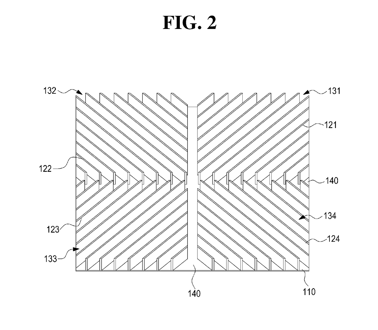
[0064]Hereinafter, the heat dissipation device 100, according to the present invention, will be described with reference to FIGS. 2 and 3.
[0065]Referring to FIGS. 2 and 3, the heat dissipation device 100, according to the first embodiment, may include inset portions 140 crossing each other and four heat dissipation areas 131, 132, 133, and 134 divided from each other with respect to the inset portions 140. Specifically, the heat dissipation device 100 may include: the inset portions 140 formed on a square plate 110 in a horizontal direction and in the direction perpendicular to the horizontal direction to cross each other in the shape of “+”; and the first to fourth heat dissipation areas 131, 132, 133, and 134 divided from each other with respect to the inset portions 140. In the present invention, based on FIG. 3, the upper left heat dissipation area may be referred to as the first heat dissipation area 131, the upper right heat dissipation area in the clockwise direction may be r...
second embodiment
[0074]Hereinafter, the heat dissipation device 100, will be described with reference to FIGS. 4 and 5.
[0075]The heat dissipation device 100 according to the second embodiment of the present invention differs from the heat dissipation device 100 according to the first embodiment described above in terms of the angles of first to fourth heat dissipation fins 121, 122, 123, and 124 formed in first to fourth heat dissipation areas 131, 132, 133, and 134. Accordingly, in describing the second embodiment of the present invention, the preceding embodiment may be applied to contents or configurations identical with those described above. Furthermore, the following description will be focused on a difference therebetween while the preceding embodiment is applied to contents identical with those described above.
[0076]Referring to FIGS. 4 and 5, the heat dissipation device 100, according to the second embodiment, may include inset portions 140 crossing each other in the shape of “+” on a plat...
third embodiment
[0080]Hereinafter, the heat dissipation device 100, will be described with reference to FIGS. 6 and 7.
[0081]The heat dissipation device 100 according to the third embodiment of the present invention differs from the heat dissipation device 100 according to the first or second embodiment described above in terms of the shape in which a plate 110 is installed, the shape in which inset portions cross each other, and the angles by which first to fourth heat dissipation fins 121, 122, 123, and 124 are formed in first to fourth heat dissipation areas 131, 132, 133, and 134.
[0082]Referring to FIGS. 6 and 7, in the heat dissipation device 100, according to the third embodiment of the present invention, the inset portions 140 may be formed on the square plate 110 to connect corners of the square plate and to cross each other. Namely, the inset portions 140 formed of two inset lines may be formed on the plate 110 to cross each other in the shape of “X.”
[0083]The plate 110 may be divided into...
PUM
| Property | Measurement | Unit |
|---|---|---|
| angle | aaaaa | aaaaa |
| angle | aaaaa | aaaaa |
| angles | aaaaa | aaaaa |
Abstract
Description
Claims
Application Information
 - R&D
- Intellectual Property
- Life Sciences
- Materials
- Tech Scout
- Unparalleled Data Quality
- Higher Quality Content
- 60% Fewer Hallucinations
Browse by: Latest US Patents, China's latest patents, Technical Efficacy Thesaurus, Application Domain, Technology Topic, Popular Technical Reports.
© 2025 PatSnap. All rights reserved.Legal|Privacy policy|Modern Slavery Act Transparency Statement|Sitemap|About US| Contact US: help@patsnap.com


