
Time of flight mass spectrometer

a mass spectrometer and time of flight technology, applied in the field of time of flight (“ tof”) mass spectrometers, can solve the problems of difficult and/or expensive practice, and achieve the effect of more physical compactness

Active Publication Date: 2017-04-06
SHIMADZU CORP
View PDF17 Cites 26 Cited by
  • Summary
  • Abstract
  • Description
  • Claims
  • Application Information

AI Technical Summary

Benefits of technology

The patent describes a method to improve the alignment between an isochronous plane and a detection plane in a time-of-flight mass spectrometer without requiring very high mechanical tolerances. This allows for the construction of lighter and cheaper designs of the mass spectrometer with high resolving powers. The method involves modifying the voltages applied to tilt correction electrodes to improve the alignment measure and obtain better results compared to previous methods.

Problems solved by technology

So, by correcting a previous angular misalignment between the isochronous plane and the detection plane in this way, a TOF mass spectrometer with high resolving power can be built without the need for very high mechanical tolerances (which as noted above can be difficult and / or expensive to achieve in practice).

Method used


Image

  • Time of flight mass spectrometer
  • Time of flight mass spectrometer
  • Time of flight mass spectrometer

Examples


examples

[0099]Simulation 1: Single Y-Dipole Field

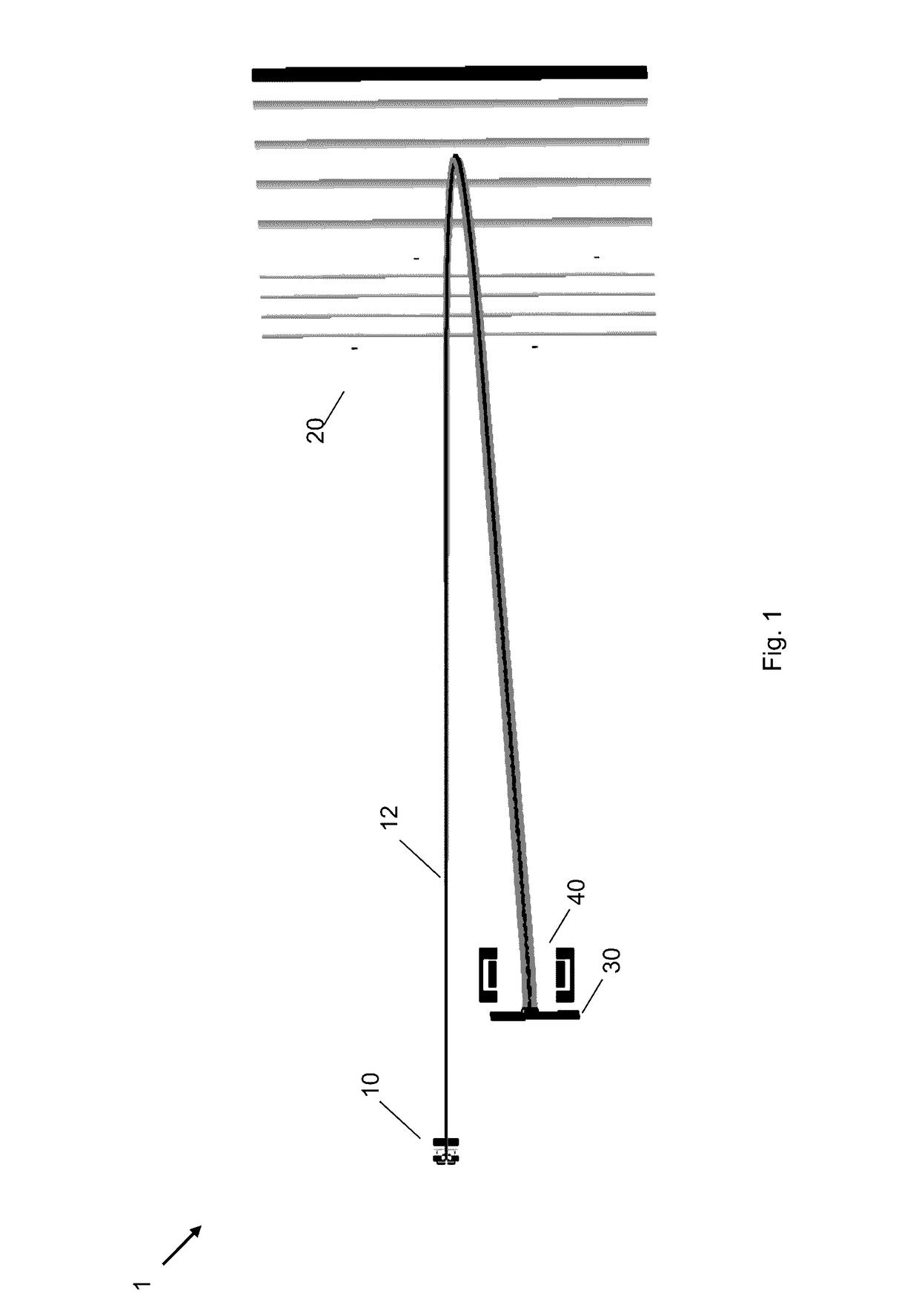
[0100]In a first example, with reference to FIG. 1 above, the detector 30 was tilted along the y-axis by 1 unwanted degree. Initial ion conditions were defined to an extent of one standard deviation within 6 dimension phase space of initial ion spatial and energy coordinates, that is dx, dy, dz, dEx, dEy, dEz. With perfect alignment of the detector plane and the isochronous plane, the instrument resolving power for a particular TOF system was determined by the simulation to be 53.2 k

[0101]The ion arrival times are shown in FIGS. 5A and 5B; without applying the correcting y-dipole the dEy arrival times are stretched to 3.08 ns due to the 1 degree tilt of the detector, resulting in a drop in instrument resolving power from 53.2 k to 11.7 k, see FIG. 5A. When ±179.5 V was applied to the y-dipole electrodes this arrival time distribution reduces to 0.68 ns, thus completely restoring the instrument resolving power to 53.2 k.

[0102]Simulation 2: Sup...


PUM


Abstract

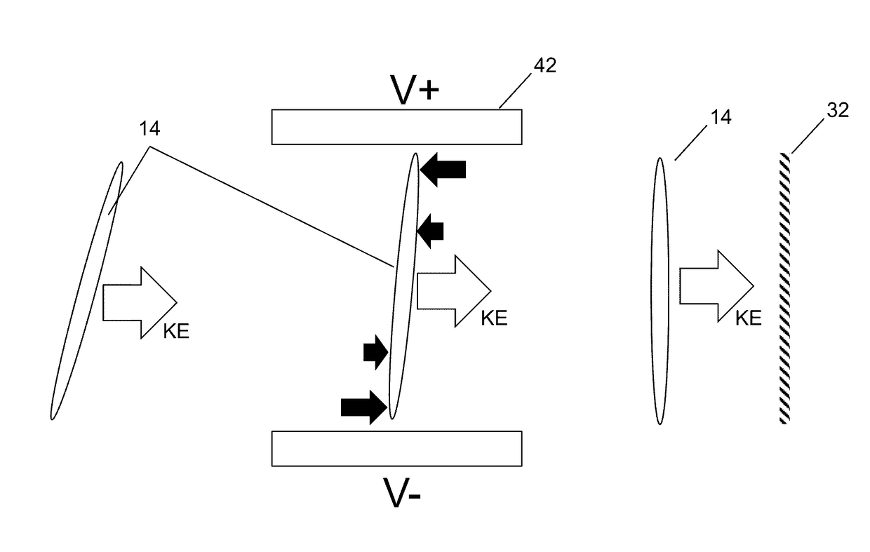
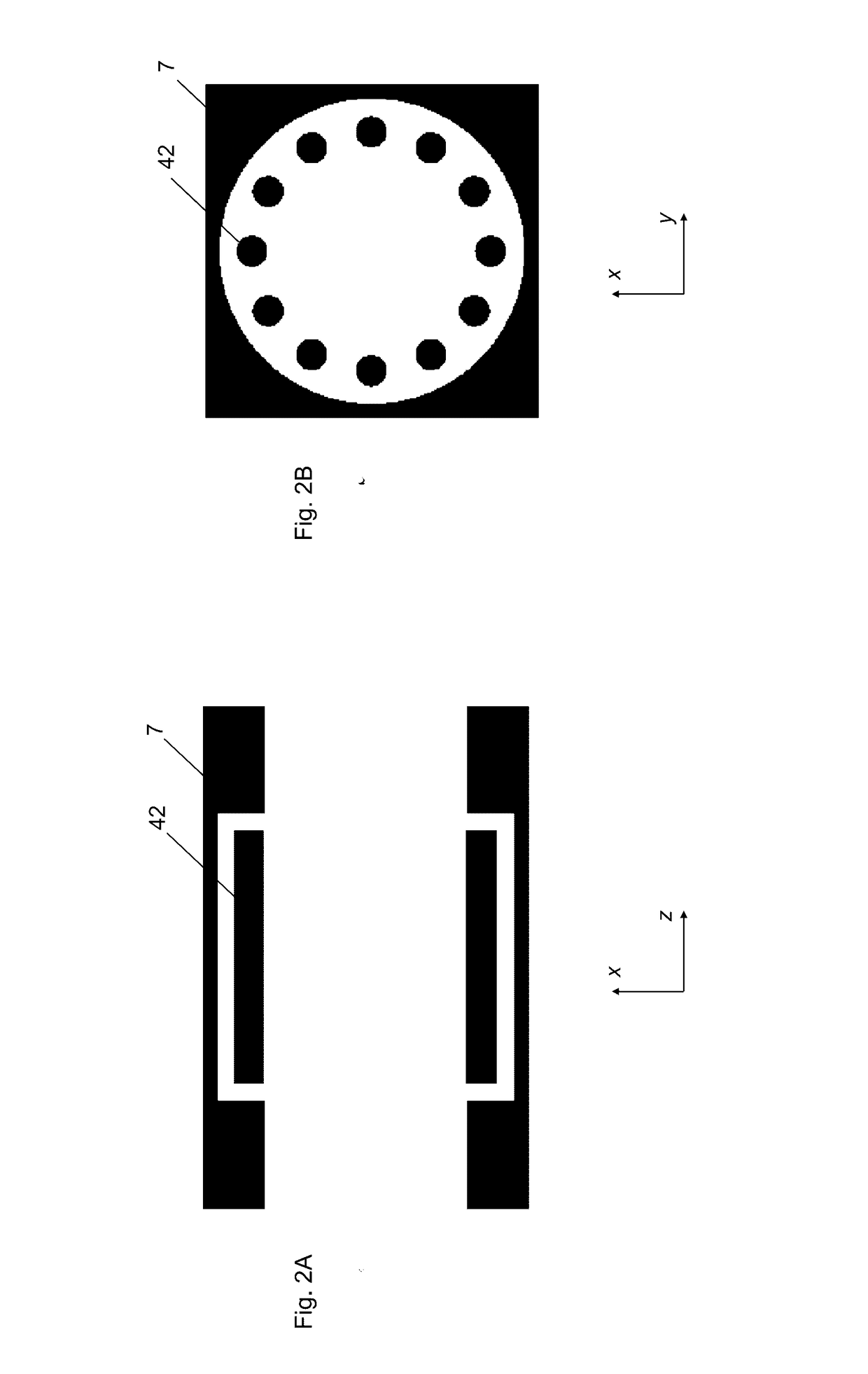
A time of flight (“TOF”) mass spectrometer including: an ion source configured to produce ions having a plurality of m / z values; a detector for detecting ions produced by the ion source; a tilt correction device located along a portion of a reference ion flight path extending from the ion source to a planar surface of the detector; wherein the tilt correction device includes tilt correction electrodes configured to generate at least one dipole electric field across the reference ion flight path, the at least one dipole electric field being configured to tilt an isochronous plane of ions produced by the ion source so as to correct a previous angular misalignment between the isochronous plane and the planar surface of the detector.

Description

FIELD OF THE INVENTION[0001]This invention relates to a time of flight (“TOF”) mass spectrometer.BACKGROUND[0002]A typical time of flight (“TOF”) mass spectrometer 101 is shown in FIG. 8.[0003]The TOF mass spectrometer includes ion source 110, a source lens 111, an ion mirror 120 and a detector 130. Ideally, ions having a given m / z are focused by the ion mirror 120 to a planar surface of the detector 130 so that the ions having the given m / z value all reach the planar surface of the detector 130 at the same time. In other words, the ions having the given m / z value are preferably focused so that the isochronous plane of the ions having the given m / z value is angularly aligned with the planar surface of the detector 130. If however, there is an angular misalignment between the isochronous plane and the planar surface of the detector 130, e.g. by virtue of a mechanical alignment error between the detector 130 and the ion mirror 120, or to a lesser extent between the detector 130 and th...

Claims


Application Information

Patent Timeline
Patent Type & Authority Applications(United States)
IPC IPC(8): H01J49/06H01J49/40
CPCH01J49/40H01J49/063
Inventor STEWART, HAMISH IANGILL, MATTHEWGILES, ROGER
Owner SHIMADZU CORP
Learn More