
Electronically slip-controllable braking system

a technology of braking system and electronic control, which is applied in the direction of braking system, vehicle components, transportation and packaging, etc., can solve the problems of relatively low braking performance of the convertible rear axle, relatively long braking distance for the vehicle, and relatively low braking performance that can be implemented by the vehicle, so as to achieve a high degree of design freedom

Active Publication Date: 2020-03-31
ROBERT BOSCH GMBH
View PDF5 Cites 0 Cited by
  • Summary
  • Abstract
  • Description
  • Claims
  • Application Information

AI Technical Summary

Benefits of technology

[0014]An electronically pressure-controllable vehicle braking system in accordance with the present invention may be equipped, in addition to the primary and secondary actuator suite, with a third actuator suite that, according to the present invention, is of simple configuration, physically compact, easy to integrate into an existing brake circuit, and can be implemented in correspondingly inexpensive fashion.
[0015]According to the present invention, the third actuator suite is connected in series, in terms of flow engineering, with the second actuator suite or secondary actuator suite disposed upstream from the third actuator suite, and with the first actuator suite or primary actuator suite disposed downstream from the third actuator suite, of the braking system. This placement of the third actuator suite is advantageous because as a result, the actuator suites can be disposed in physical proximity to one another in the vehicle, short line connections are sufficient for electrical and hydraulic connection of the actuator suites, and an additional installation outlay or installation space requirement in the vehicle can be minimized.
[0018]The third actuator suite can furthermore be embodied on a hydraulic assemblage of the primary actuator suite or on a housing of the secondary actuator suite, or can have a separate actuator housing. The electronic control device of the primary actuator suite and / or of the secondary actuator suite can likewise be grouped together with the one for the third actuator suite, or control devices that are respectively separate from and networked with one another can be used. The present invention thus makes possible a high level of design freedom in terms of its implementation.

Problems solved by technology

This convertible rear axle braking performance is comparatively low as a result of the dynamic axle load shift toward the front axle that takes place, due to inertia, in the course of a braking operation.
Given the property of the secondary actuator suite, as explained, of being able to act upon all the existing wheel brakes only with a uniform brake pressure, in combination with a low brake pressure that can be converted by the wheel brakes of the rear axle without a risk of locking the associated wheels, the result in the case of a braking operation in which brake pressure is applied by the secondary actuator suite, because a malfunction has occurred in the primary actuator suite, is the disadvantage that the total braking performance that can be implemented by the vehicle is relatively low, consequently resulting in a relatively long braking distance for the vehicle.
This has a particularly negative effect in vehicles in which the dynamic axle load shift toward the front axle in the context of a braking operation is particularly large.

Method used


Image

  • Electronically slip-controllable braking system

Examples


Embodiment Construction

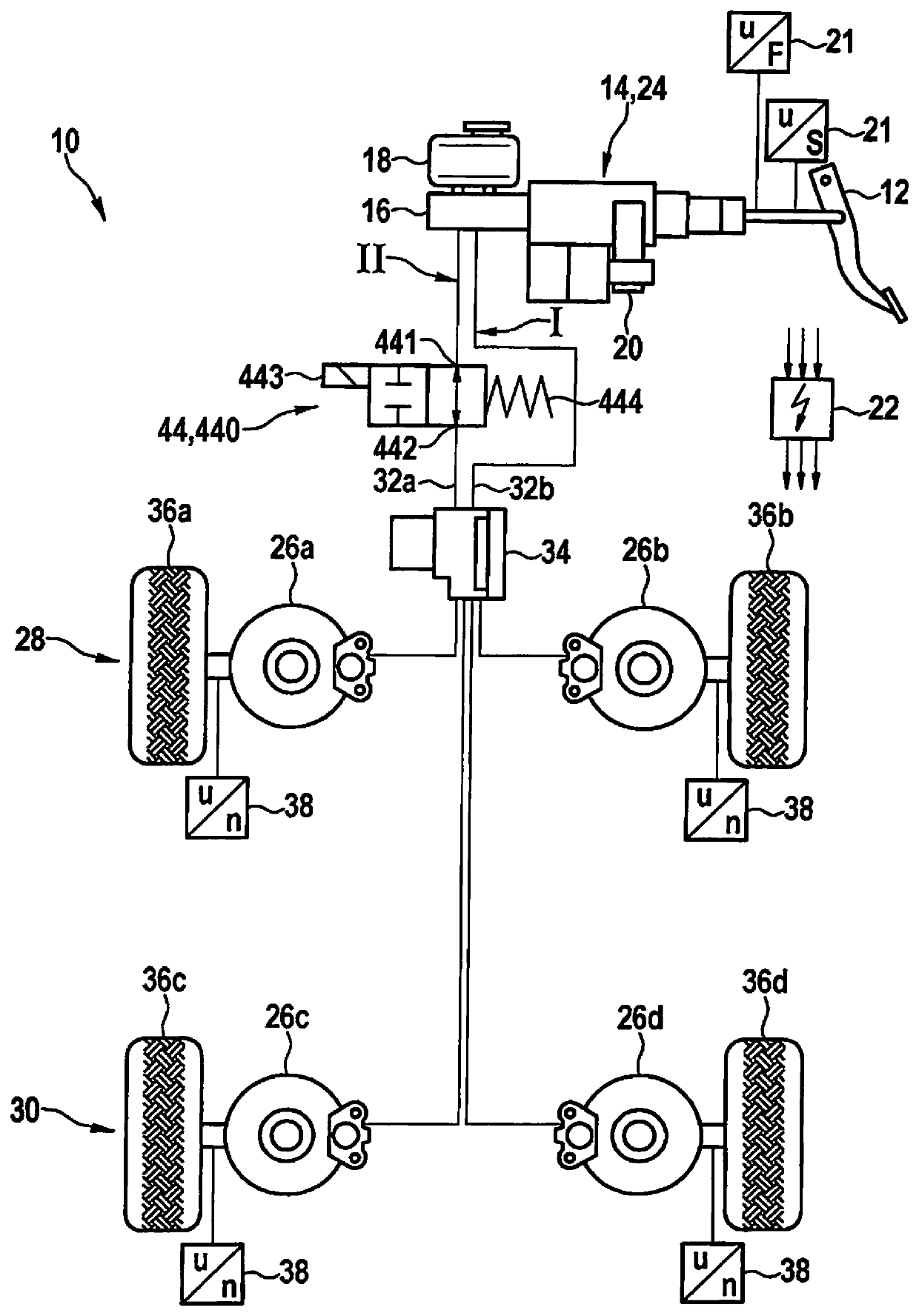
[0021]The electronically slip-controllable braking system 10 as shown in the single FIGURE encompasses, inter alia, an actuation unit 14 actuatable via a brake pedal 12 by a driver via muscle force, and a brake master cylinder 16, acted upon by that actuation unit 14, which is supplied with hydraulic pressure medium via an attached reservoir 18. Actuation unit 14 is equipped with an electronically controllable actuator 20 with which, for example, the braking force applied by the driver can be boosted by an external force. This actuator 20 is, for example, an electronically controllable electric motor having a downstream linkage. Control is applied to the electric motor as a function of the actuation of brake pedal 12. Provided for this purpose on brake pedal 12 are sensors 21 which detect the actuation force and / or actuation travel, and thus a braking input, of a driver, and whose sensor signals are evaluated by an electronic control device 22 in order to calculate the control appli...


PUM


Abstract

An electronically slip-controllable vehicle braking system for a motor vehicle, including an actuatable brake master cylinder, to which at least one wheel brake that is associated with one wheel of a front axle of the vehicle, and at least one wheel brake that is associated with one wheel of a rear axle of the motor vehicle, are detachably connected. An electronically controllable first actuator suite of the braking system establishes and regulates mutually differing brake pressures in the wheel brakes as a function of the respectively existing slip conditions. An electronically controllable second actuator suite establishes and regulates a uniform brake pressure at the wheel brakes, and a third actuator suite limits the brake pressure generated by the second actuator suite at the at least one wheel brake associated with the wheel of the rear axle. Electronic control application to the actuator suites is accomplished via an electronic control device.

Description

CROSS REFERENCE[0001]The present application claims the benefit under 35 U.S.C. § 119 of German Patent Application No. DE 102016221444.6 filed on Nov. 2, 2016, which is expressly incorporated herein by reference in its entirety.FIELD[0002]The present invention relates to an electronically slip-controllable braking system.BACKGROUND INFORMATION[0003]An electronically slip-controllable braking system is described in German Patent Application No. DE 10 2009 001135 A1.[0004]This braking system encompasses an electronically controllable first actuator suite, referred to below as a “primary” actuator suite, in the form of a conventional ABS / ESP brake system for individual-wheel modulation of brake pressure as a function of the slip conditions existing at the wheels. The brake pressures of the individual wheel brakes can be adjusted or regulated independently of one another. In conjunction with a conventional four-wheeled motor vehicle, this is therefore referred to as a “four-channel regu...

Claims


Application Information

Patent Timeline
Patent Type & Authority Patents(United States)
IPC IPC(8): B60T8/48B60T13/66B60T8/26B60T13/14B60T13/68
CPCB60T13/146B60T8/266B60T8/489B60T13/662B60T8/268B60T13/686B60T8/48B60T13/745
Inventor STREHLE, ALFREDFLINNER, MARKOSCHANZENBACH, MATTHIASSCHMIDT, THOMAS
Owner ROBERT BOSCH GMBH
Learn More