
Ultrasound system and method for use with a heat-affected region

a technology of ultrasonic imaging and heat-affected regions, applied in applications, ultrasonic/sonic/infrasonic image/data processing, ultrasonic/sonic/infrasonic diagnostics, etc., can solve the problems of incomplete electrical isolation, undesirable incomplete electrical isolation, and inability to leave viable cancer cells or incomplete electrical isolation

Inactive Publication Date: 2017-04-13
GENERAL ELECTRIC CO
View PDF4 Cites 42 Cited by
  • Summary
  • Abstract
  • Description
  • Claims
  • Application Information

AI Technical Summary

Benefits of technology

This patent describes a method and system for ultrasound imaging that can detect and measure changes in tissue caused by heat. By analyzing the ultrasound data and comparing it to a pilot trace, the system can accurately determine the size and location of a heat-affected region in real-time. This information can be displayed on the screen and used to inform medical professionals about the status of a patient's tissue. This technology helps improve the accuracy and reliability of ultrasound imaging, making it a more useful tool in medical diagnosis and treatment.

Problems solved by technology

Not generating a high enough temperature during a thermal ablation procedure may result in an incomplete ablation, potentially leaving viable cancer cells or incomplete electrical isolation.
A procedure that leaves viable cancer cells or results in incomplete electrical isolation is undesirable and may require one or more additional follow-up procedures in order achieve the desired clinical outcome.
Achieving too high of a temperature through thermal ablation may also result in negative effects.
For example, too high of a temperature may result in collateral damage to nearby organs.
Too high of a temperature may cause both short-term and long-term problems.
For example, the ablation may result in too much tissue being destroyed.
This may damage nearby organs and / or have catastrophic effects such as major bleeding.

Method used


Image

  • Ultrasound system and method for use with a heat-affected region
  • Ultrasound system and method for use with a heat-affected region
  • Ultrasound system and method for use with a heat-affected region

Examples


Embodiment Construction

[0014]In the following detailed description, reference is made to the accompanying drawings that form a part hereof, and in which is shown by way of illustration specific embodiments that may be practiced. These embodiments are described in sufficient detail to enable those skilled in the art to practice the embodiments, and it is to be understood that other embodiments may be utilized and that logical, mechanical, electrical and other changes may be made without departing from the scope of the embodiments. The following detailed description is, therefore, not to be taken as limiting the scope of the invention.

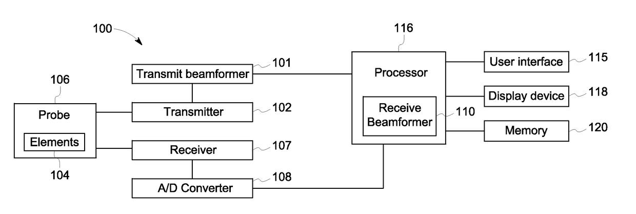
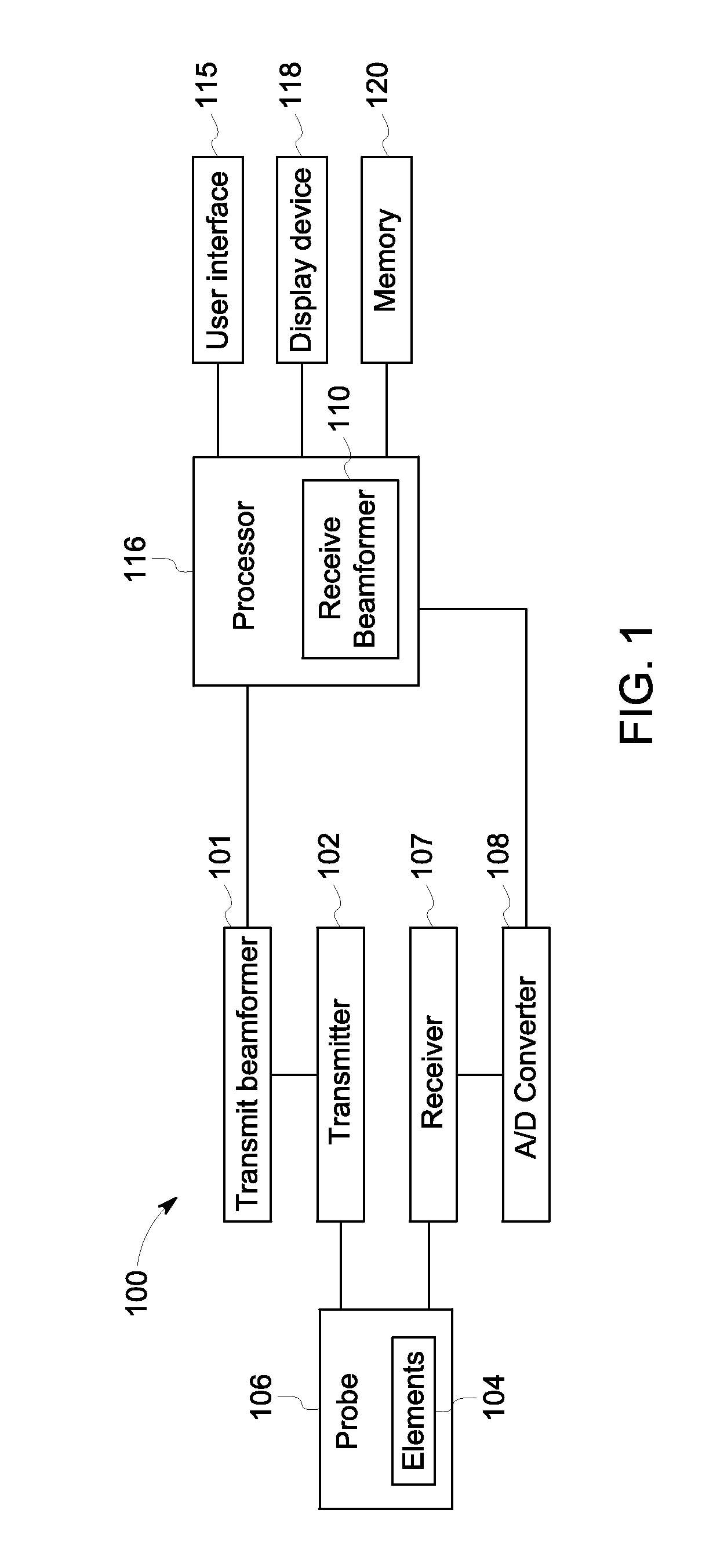
[0015]FIG. 1 is a schematic diagram of an ultrasound imaging system 100 in accordance with an embodiment. The ultrasound imaging system 100 includes a transmit beamformer 101 and a transmitter 102 that drive elements 104 within a probe 106 to emit pulsed ultrasonic signals. The probe 106 may be any type of probe, including a linear probe, a curved array probe, a 1.25D array pr...


PUM


Abstract

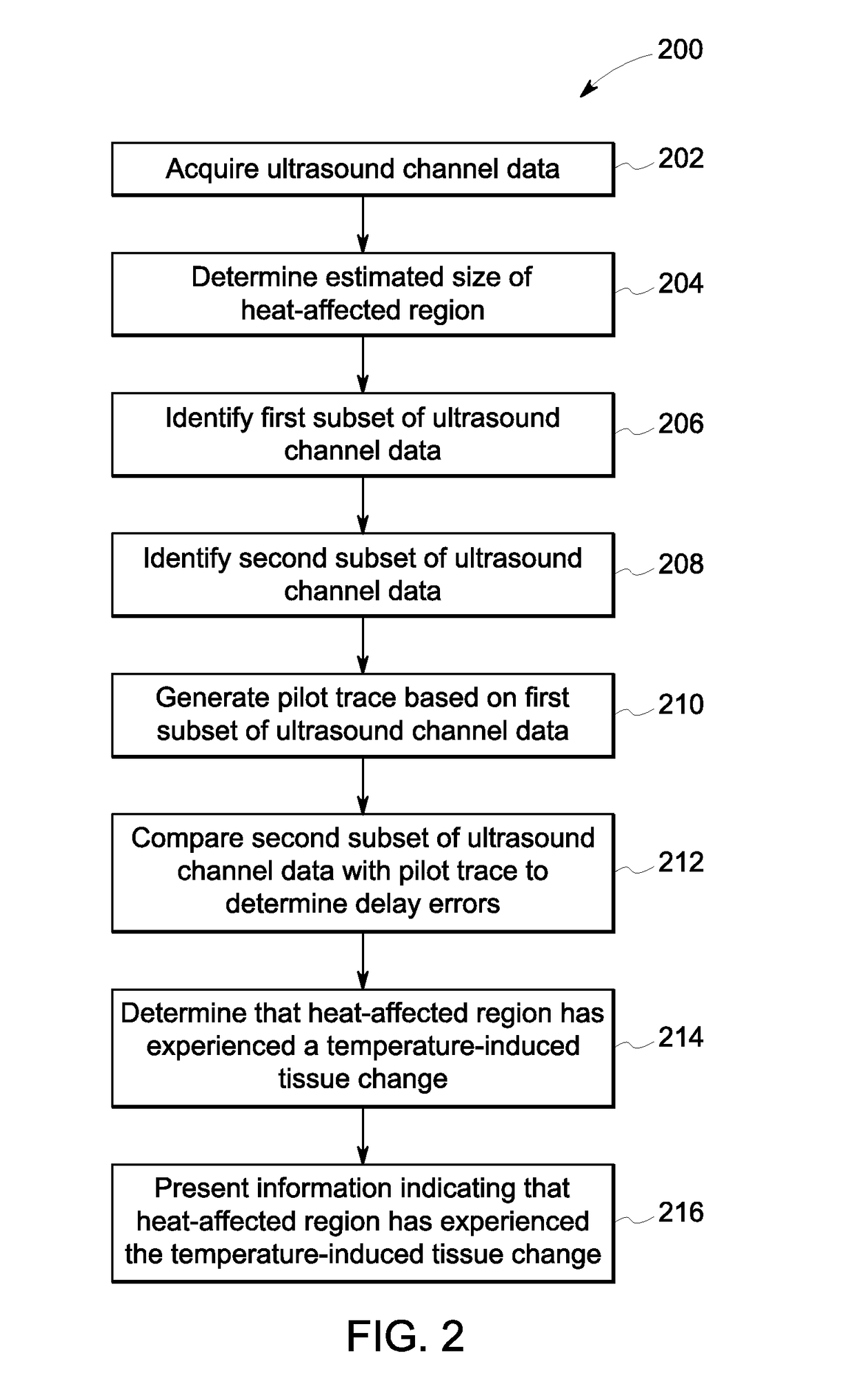
A method and system of ultrasound imaging includes acquiring ultrasound channel data for a region-of-interest, determining an estimated size of a heat-affected region, identifying a first subset of the ultrasound channel data, and identifying a second subset of the ultrasound channel data. The method and system includes generating a pilot trace based on the first subset of ultrasound channel data and comparing the second subset of the ultrasound channel data to the pilot trace to determine delay errors for the second subset of the ultrasound channel data. The method and system includes determining that the heat-affected region has experienced a temperature-induced tissue change based on the delay errors and the estimated size of the heat affected region, and presenting information indicating that the heat-affected region has experienced the temperature-induced tissue change.

Description

FIELD OF THE INVENTION[0001]This disclosure relates generally to an ultrasound imaging system and method for determining that a heat-affected region has experienced a temperature-induced tissue change.BACKGROUND OF THE INVENTION[0002]Thermal ablation is clinically used both for cancer treatment and for the treatment of cardiac irregularities, such as a cardiac arrhythmia. Thermal ablation is used to kill cancerous cells during cancer treatment and to create isolation scars in order to disrupt abnormal electrical pathways in order to treat cardiac arrhythmia. Accurate and precise temperature control is important during a thermal ablation procedure. It is important to raise the tissue to a high enough temperature in order to create irreversible tissue damage, such as that which would be required either to kill cancer cells or to create an isolation scar. Not generating a high enough temperature during a thermal ablation procedure may result in an incomplete ablation, potentially leavi...

Claims


Application Information

Patent Timeline
Patent Type & Authority Applications(United States)
IPC IPC(8): A61B8/08A61B8/00
CPCA61B8/08A61B8/463A61B8/5223A61B8/5238A61B2018/00684A61B8/54A61B2018/00577A61B2018/00791A61B8/4444A61B8/0833A61B8/44A61B8/461A61B8/085A61B8/5246A61B18/1492G16H50/30
Inventor EIGIL, SAMSETHAUGEN, GEIR ULTVEITPASTERNAK, MARGOT
Owner GENERAL ELECTRIC CO
Learn More