

Image forming system and program
a technology of image forming and program, applied in the field of image forming system, to achieve the effect of preventing unauthorized access
- Summary
- Abstract
- Description
- Claims
- Application Information
AI Technical Summary
Benefits of technology
Problems solved by technology
Method used
Image

Examples
first embodiment
1. First Embodiment
1-1. Overview of Configuration
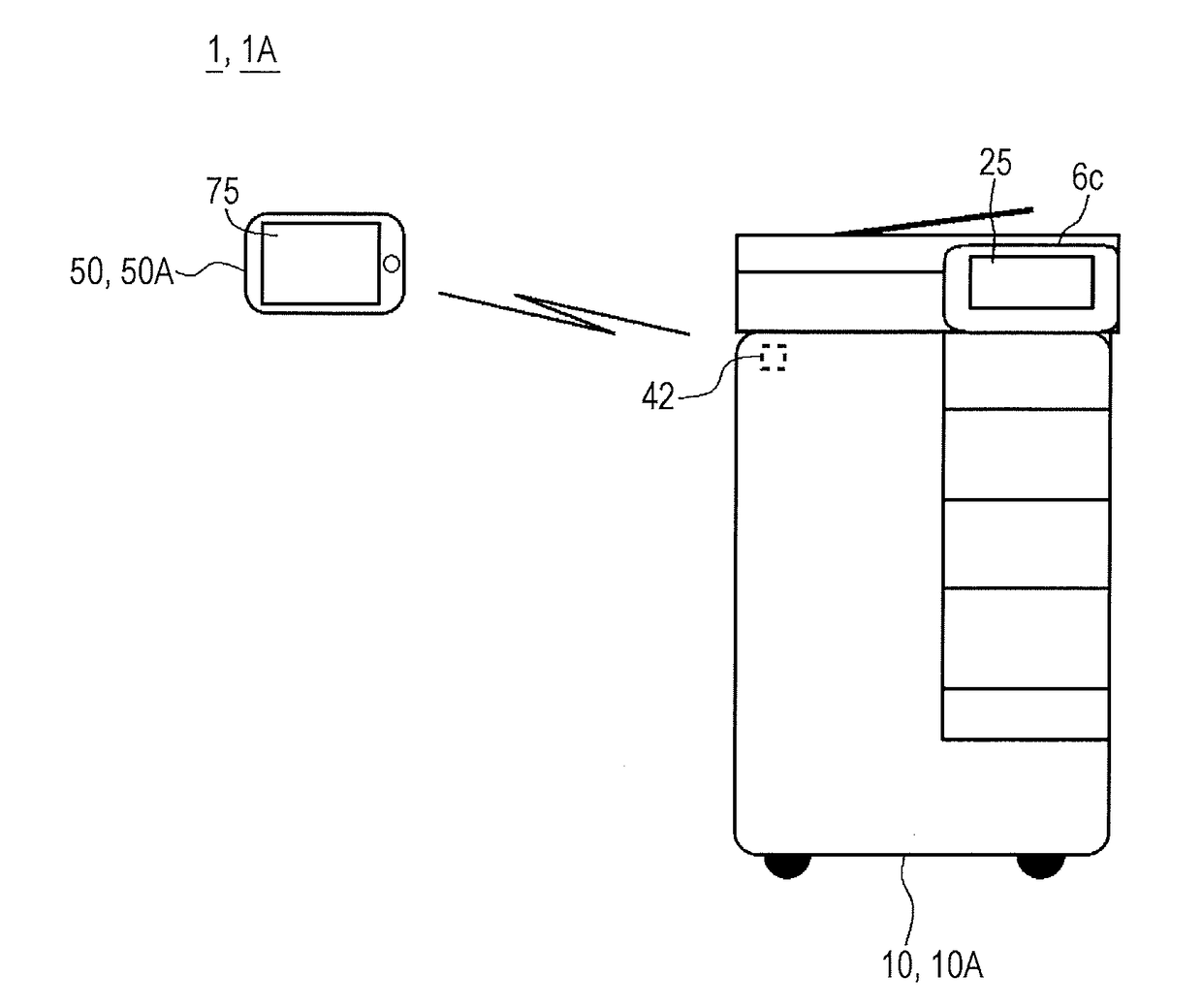
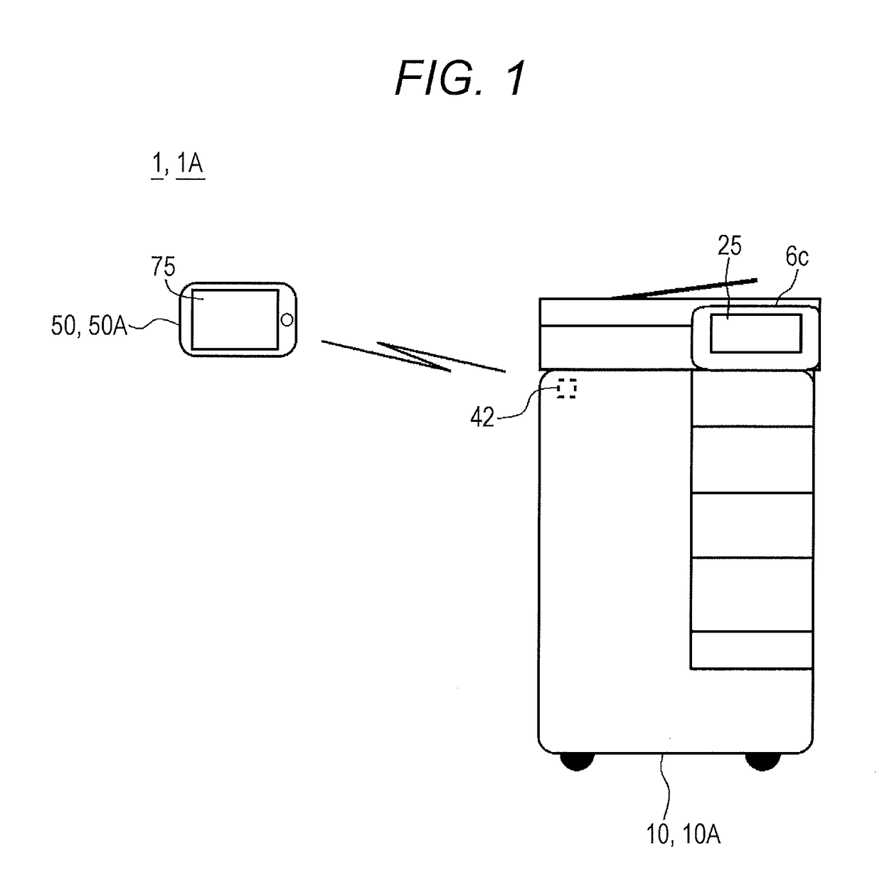
[0065]FIG. 1 shows an image forming system 1 (also referred to as “1A”) according to a first embodiment. As shown in FIG. 1, the image forming system 1 (1A) includes an MFP (image forming device) 10 (10A) and a portable terminal 50 (50A).
[0066]The MFP 10 and the portable terminal 50 are wirelessly connected to each other by using various wireless communication techniques. For example, short-range wireless communication and communication using a wireless LAN (e.g., IEEE 802.11) can be used for communication between the MFP 10 and the portable terminal. In this embodiment, as the short-range wireless communication, communication using a Bluetooth (registered trademark) method (Bluetooth communication) is used. More specifically, as the Bluetooth communication, communication using a BLE (Bluetooth Low Energy) method (also referred to as “BLE communication”) is employed. Note that the image forming system 1 is also referred to as “communi...
second embodiment
2. Second Embodiment
[0141]A second embodiment is a modification example of the first embodiment. A difference from the first embodiment will be mainly described below.
[0142]In the above first embodiment, existence of a user who possesses the portable terminal 50 in the vicinity of the MFP 10 is confirmed by using a two-dimensional barcode.
[0143]In the second embodiment, existence of a user who possesses the portable terminal 50 in the vicinity of the MFP 10 is confirmed by using an NFC tag.
[0144]An MFP 10 (10B) according to the second embodiment (see FIG. 13) also includes an NFC tag 7. The NFC tag 7 is provided in the vicinity of, for example, a surface of the operation panel unit 6c of the MFP 10 (or a main body unit or the like of the MFP 10). In the NFC tag 7, for example, device identification information (e.g., MAC address) of the MFP 10 is embedded.
[0145]FIG. 14 is a flowchart showing operation of an application 120 (also referred to as “120B”) of a portable terminal 50 (also...
third embodiment
3. Third Embodiment
[0156]A third embodiment is a modification example of the first embodiment. A difference from the first embodiment will be mainly described below.
[0157]In the above first embodiment, existence of a user who possesses the portable terminal 50 in the vicinity of the MFP 10 is confirmed by using a two-dimensional barcode.
[0158]In the third embodiment, existence of a user who possesses the portable terminal 50 in the vicinity of the MET 10 is confirmed by using an IC card (IC card possessed by the user of the portable terminal 50). The IC card is, for example, a contactless IC card such as “Suica” (registered trademark).
[0159]An MFP 10 (10C) according to the third embodiment (see FIG. 16) also includes an IC card reader 8. The IC card reader 8 is provided in the vicinity of, for example, a surface of the operation panel unit 6c of the MFP 10 (or a main body unit or the like of the MFP 10). As described below, information in an IC card (card identification information ...
PUM
 Abstract
Description
Claims
Application Information