Enhanced tone mapper for high dynamic range images and video

a tone mapper and dynamic range technology, applied in image enhancement, color signal processing circuits, instruments, etc., can solve problems such as image details loss, and achieve the effects of preserving or enhancing image details, reducing image luminance ranges, and increasing image luminance ranges

Active Publication Date: 2017-04-13
STMICROELECTRONICS ASIA PACIFIC PTE
View PDF9 Cites 49 Cited by
  • Summary
  • Abstract
  • Description
  • Claims
  • Application Information

AI Technical Summary

Benefits of technology

[0005]The present disclosure provides a color tone mapping module configured to decrease a luminance range of an image or video from a high dynamic range to a standard dynamic range, and an inverse color tone mapping module configured to increase a luminance range of an image or video from a standard dynamic range to a high dynamic range, while preserving or enhancing image details.
[0007]According to one embodiment, an inverse tone mapping module receives standard dynamic range red, green, blue values of an image or video. The inverse tone mapping module includes a RGB to Y / I / V module, a sub-band divider, an adaptive boost control module, a saturation control module, a SDR-HDR mapping module, and a de-banding filter. The RGB to Y / I / V module converts the standard dynamic range red, green, blue values to luminance values. The sub-band divider determines low and high spatial frequency components of the luminance values. The adaptive boost control module uses the low and high spatial frequency components to determine a gain value. The gain value is applied to the standard dynamic range red, green, blue values to obtain enhanced range red, green, blue values. The saturation control module prevents out of gamut values of the enhanced range red, green, blue values from being clipped and causing false colors in the image or video. The SDR-HDR mapping module maps the saturated controlled red, green, blue values to high dynamic range red, green, blue values. The de-banding filter module filters banding noise from the high dynamic range red, green, blue values. The high dynamic range red, green, blue values are then outputted from the de-banding filter module.
[0008]The tone mapping module and the inverse tone mapping module disclosed herein results in tone mapping of images and video from one dynamic range to another dynamic range while preserving or enhancing image details.

Problems solved by technology

However, many display devices, such as cathode ray tubes and liquid crystal displays, are capable of displaying only standard or enhanced dynamic ranges, not high dynamic ranges.
However, compressing an image or video from a high dynamic range to a lower dynamic range, such as an enhanced or standard dynamic range, often results in loss of image details.

Method used


Image

  • Enhanced tone mapper for high dynamic range images and video
  • Enhanced tone mapper for high dynamic range images and video
  • Enhanced tone mapper for high dynamic range images and video

Examples


first embodiment

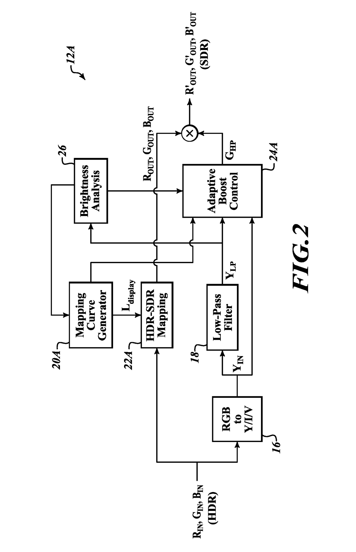
[0028]FIG. 2 is a block diagram illustrating an example of a tone mapping module 12A according to principles disclosed herein. The tone mapping module 12A decreases the luminance of the image or video from the high dynamic range to the standard dynamic range, while preserving or enhancing image details. The tone mapping module 12A includes an RGB to Y / I / V module 16, a low-pass filter module 18, a mapping curve generator module 20A, a HDR-SDR mapping module 22A, and adaptive boost control module 24A, and a brightness analysis module 26.

[0029]The tone mapping module 12A receives high dynamic range red, green, blue values RIN, GIN, BIN of an image or video from the source. In one embodiment, the high dynamic range red, green, blue values RIN GIN, BIN is included in an array, where each red, green, blue value corresponds to a pixel. In other embodiments, the high dynamic range red, green, blue values RIN, GIN, BIN are represented as bits. The invention, however, is not limited to any pa...

second embodiment

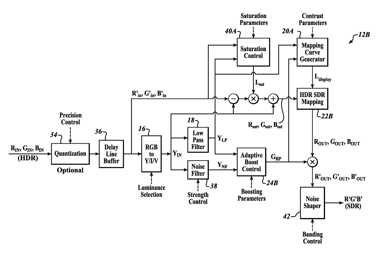
[0048]FIG. 4 is a block diagram illustrating an example of a tone mapping module 12B according to principles disclosed herein. Similar to the tone mapping module 12A, the tone mapping module 12B includes the RGB to Y / I / V module 16, the low-pass filter module 18, and the mapping curve generator module 20A. In addition, the tone mapping module 12B includes a quantization module 34, a delay line buffer module 36, a noise filter module 38, a saturation control module 40A, a HDR-SDR mapping module 22B, an adaptive boost control module 24B, and a noise shaper module 42.

[0049]Similar to the tone mapping module 12A, the tone mapping module 12B receives high dynamic range red, green, blue values RIN, GIN, BIN of an image or video from the source.

[0050]The quantization module 34 quantizes the high dynamic range red, green, blue values RIN , GIN, BIN to compress the number of values and improve processing time. The quantization module 28 is not limited any particular method, and any suitable m...

third embodiment

[0064]FIG. 5 is a block diagram illustrating an example of a tone mapping module 12C according to principles disclosed herein. Similar to the tone mapping module 12B, the tone mapping module 12C includes the quantization module 34, the delay line buffer module 36, the RGB to Y / I / V module 16, the low-pass filter module 18, noise filter module 38, the adaptive boost control module 24B, the mapping curve generator module 20A, the HDR-SDR mapping module 22B, the saturation control module 40A, and the noise shaper module 42. However, in contrast to the tone mapping module 12B, the saturation control module 40A is positioned subsequent to the mapping by the HDR-SDR mapping module 22B. That is, the saturation control module 40A limits the saturation gain of the standard dynamic range red, green, blue values ROUT, GOUT, BOUT from the HDR-SDR mapping module 22B.

[0065]FIG. 6 is a block diagram illustrating an example of a third embodiment of a tone mapping module 12D according to principles d...


PUM


Abstract

Various embodiments provide tone mapping of images and video from one dynamic range to an available dynamic range of a display device while preserving or enhancing image details. According to one embodiment, an enhanced tone mapping module is configured to decrease a luminance of an image or video from a high dynamic range to a standard dynamic range. Conversely, according to one embodiment, an enhanced inverse tone mapper to increase a luminance of an image or video from a standard dynamic range to a high dynamic range.

Description

TECHNICAL FIELD[0001]The present disclosure is directed to tone mapping of images and video from one dynamic range to another and luminance contrast enhancement to preserve or enhance image and video details during mapping.DESCRIPTION OF THE RELATED ART[0002]Luminance represents the pixel brightness of an image or video. The dynamic range, or contrast ratio, of an image or video is the luminance difference between the darkest and lightest portions of the image or video. In general, standard dynamic range (SDR) is less than or equal to 10 f-stops (1024:1), enhanced dynamic range (EDR) is greater than 10 f-stops and less than or equal to 16 f-stops (65536:1), and high dynamic range (HDR) is greater than 16 f-stops (65536:1). An ultra high dynamic range (UHDR) is also available and greater ranges will continue to be made available by the advancing technology.[0003]With the demand for high quality images and video, many images and video are produced with a high dynamic range of luminosi...

Claims


Application Information

Patent Timeline
Patent Type & Authority Applications(United States)
IPC IPC(8): G09G5/06G06T5/20
CPCG09G5/06G06T5/20G06T2207/10016G06T2207/10004G06T2207/10024G09G5/02G09G5/10G09G2320/0271G09G2320/0673G09G2340/06G09G2360/16H04N5/20H04N5/144H04N5/202H04N5/57H04N5/76H04N9/68H04N9/77G06T5/008H04N11/26
Inventor HUANG, YONGHUI, LUCAS
Owner STMICROELECTRONICS ASIA PACIFIC PTE
Why Eureka
Try Eureka