
Methods and Apparatus Notifying a User of the Operating Condition of a Household Appliance

a technology for notifying users and household appliances, applied in the direction of instruments, wireless commuication services, program control, etc., can solve the problems of not waiting in close proximity to know when the operation has stopped, alarms only work, and the time it takes for a washer and dryer to complete a cycle may be unknown or easily forgotten by the user

Inactive Publication Date: 2017-04-13
TWIN HARBOR LABS
View PDF1 Cites 185 Cited by
  • Summary
  • Abstract
  • Description
  • Claims
  • Application Information

AI Technical Summary

Benefits of technology

The present invention is about methods and devices for notifying a user when an event occurs that produces sounds or vibrations with specific characteristics. The invention uses sensors to convert the sounds or vibrations into a signal that is processed to enhance the characteristics of the signal. The notification alert is sent when the processed signal satisfies predetermined conditions. The invention can be implemented using a programmed smartphone or other handheld computer carried by the user and programmed to produce output that is perceptible to the user. The invention can also be used in household appliances like washers, dryers, microwaves, stoves, and other devices to notify the user of potential interest. The distance between the appliance and the user is determined, and the notification parameters are used to activate the notification system. The technical effects of the invention include improved notification systems that can detect and respond to specific events with specific characteristics.

Problems solved by technology

However, once a user starts on operation with the washer and dryer they may not wait in close enough proximity to know when the operation has stopped.
These alarms only work if the user is close enough to hear the alarm.
The time it takes for a washer and dryer to complete a cycle may be unknown or easily forgotten by the user.
If the user, or attendant, does not attend to the laundry promptly when a washing or drying cycle is completed clothes may become moldy in the case of wet clothes or wrinkled in the case of dried clothes.
In addition, the person's work schedule may be affected by virtue of the fact that it was not known that the pertinent laundry process had ended.
Unfortunately, the current level may drop if the appliance pauses or performs other functions during normal operation.
Timing devices have been used to indicate the completion of an operation, but will be inaccurate when the appliance alters its operating cycle to adjust for special conditions; for example, some dryers have moisture sensors which automatically adjust the operation time based on the level of moisture inside the dryer.
Unfortunately, users may not like the idea of leaving a phone on a dryer where it could be stolen, and the user may want to use the phone for other reasons but can't do so when the phone must be left atop the dryer.
Additionally, having many electrical components in an apparatus to monitor the washer and dryer may not be aesthetically pleasing.
Furthermore, it is a waste of other resources which are readily available in most households.
This method and system can only be used to detect the end of cycle on a either the washer or the dryer, not both.

Method used


Image

  • Methods and Apparatus Notifying a User of the Operating Condition of a Household Appliance
  • Methods and Apparatus Notifying a User of the Operating Condition of a Household Appliance
  • Methods and Apparatus Notifying a User of the Operating Condition of a Household Appliance

Examples


first embodiment

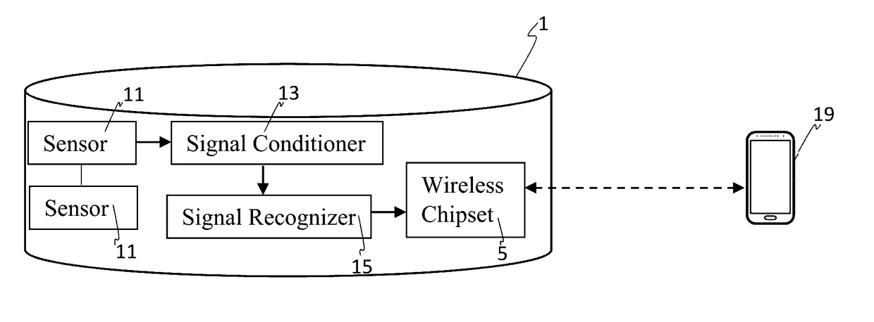
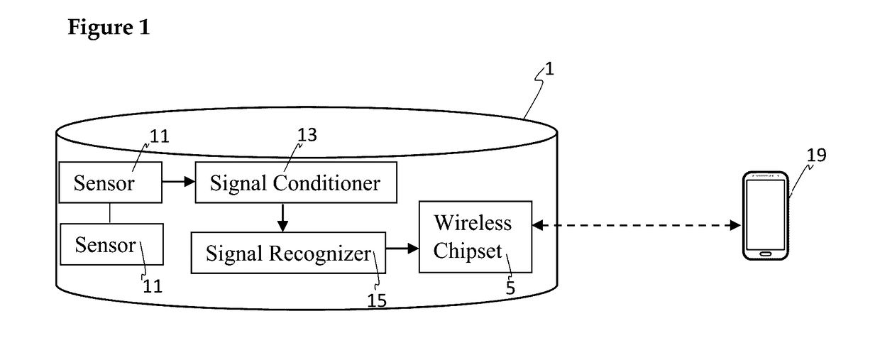
[0040]In the invention, a signal sensing and processing unit here called a “triggered signal transmitter,” indicated generally at 1 in FIG. 1, incoming sounds or vibrations from an appliance or device being monitored (not shown) are detected by one more acoustic sensors 11 whose output(s) are connected to a signal conditioner 13 whose output is monitored by a signal recognizer 15. When a predetermined signal is detected by the signal recognizer 15, a wireless notification message is transmitted by means of a wireless chipset 5 to a notification unit 19.

[0041]The triggered signal transmitter 1 receives incoming sounds or vibrations and, when those sounds or vibrations meet predetermined conditions, transmits a notification message or messages to one or more users who carry a notification unit 19 or are near to the triggered signal transmitter 1. The triggered signal transmitter 1 includes one or more sound or vibration sensors 11 which may be placed anywhere sounds or vibrations bein...

second embodiment

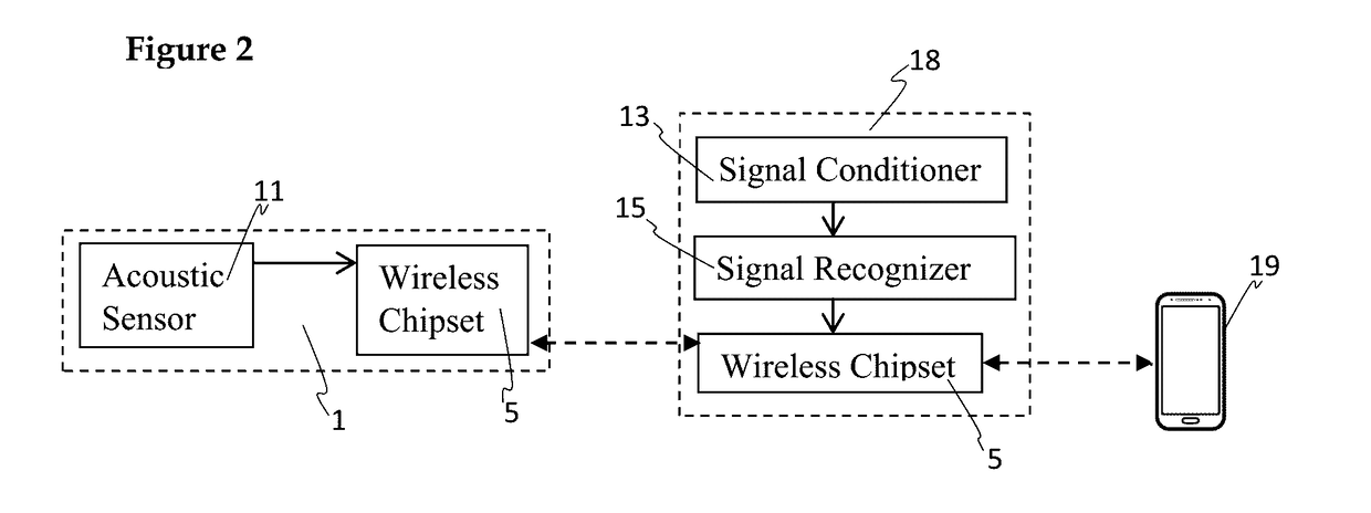
[0247]FIG. 11 illustrates the hardware and software architecture for sensing an environment and outputting notification message 30 in a An acoustic of triggered signal transmitter 1 senses environment sounds using an acoustic sensor 11. A notification unit 19 is not used in this embodiment. The triggered signal transmitter 1 conditions the signal 3 then attempts to recognize the signal 13. If the signal recognizer 15 matches a corresponding notification message 30 then that notification message 30 is sent. The wireless chipset 5 may communicate with a database 46 to send data to the signal recognizer. Alternatively memory 23 on the triggered signal transmitter 1 may contain sound patterns and templates for the signal recognizer 15 to process.

[0248]FIG. 12 provides a simplified functional block diagram which illustrates input 7 from the notification unit 19. The wireless chipset 5 can receive input 7 from the notification unit 19. The wireless chipset 5 can send the input to the sig...


PUM


Abstract

Sounds, alarms or other indications of conditions of potential interest that are produced by appliances and other household devices are detected by one or more sensors to trigger a notification signal that is sent to a remotely located user. The signals produced by the sensors are advantageously compared with a database of signals representing conditions of potential interest produced by known appliances and devices, producing the appropriate notification signal when a match is found. Notifications may be relayed to one or more selected users only when predetermined conditions are satisfied.

Description

CROSS REFERENCE TO RELATED APPLICATIONS[0001]This patent application is a Continuation-in-part application of, and claims the benefit of, U.S. patent application Ser. No. 14 / 880,883, filed on Oct. 12, 2015, now U.S. Pat. No. 9,386,140, incorporated herein by reference. U.S. Pat. No. 9,386,140 is a Continuation-in-part application of, and claims the benefit of, U.S. patent application Ser. No. 14 / 682,152, filed on Apr. 9, 2015, now U.S. Pat. No. 9,159,217, incorporated herein by reference. U.S. patent application Ser. No. 14 / 682,152 is a non-provisional application of, and claims the benefit of the filing dates of, U.S. Provisional Patent No. 62 / 027,062 filed on Jul. 21, 2014 entitled Washer Dryer Alarm and of U.S. Provisional Patent No. 61 / 977,786 filed on Apr. 10, 2014 entitled Personal Household Notification Relay Device. The disclosures of both of these provisional patent applications are incorporated herein by reference.FIELD OF THE INVENTION[0002]This invention relates to metho...

Claims


Application Information

Patent Timeline
Patent Type & Authority Applications(United States)
IPC IPC(8): H04W68/00H04W4/00H04W4/14H04M1/725H04M1/72415
CPCH04W68/00H04W4/14H04W4/008H04M1/72533G05B15/02G05B19/042G07C3/00H04M19/047H04W4/16G05B2219/24015G05B2219/24048G05B2219/24107G05B2219/2613G05B2219/2642H04W4/80H04M1/72415G05B19/0428
Inventor LOGAN, JAMES D.CARR, ERICBAKER, JR., RICHARD A.
Owner TWIN HARBOR LABS
Learn More