Method and Apparatus for Fabricating a Composite Object

Active Publication Date: 2017-04-20
LAING OROURKE AUSTRALIA PTY LTD
View PDF0 Cites 70 Cited by
  • Summary
  • Abstract
  • Description
  • Claims
  • Application Information

AI Technical Summary

Problems solved by technology

However, stereolithography, also suffers from a number of drawbacks.
However, as the curable suspension is largely homogenous, the resulting fabricated composite object has consist

Method used


Image

  • Method and Apparatus for Fabricating a Composite Object
  • Method and Apparatus for Fabricating a Composite Object
  • Method and Apparatus for Fabricating a Composite Object

Examples


Embodiment Construction

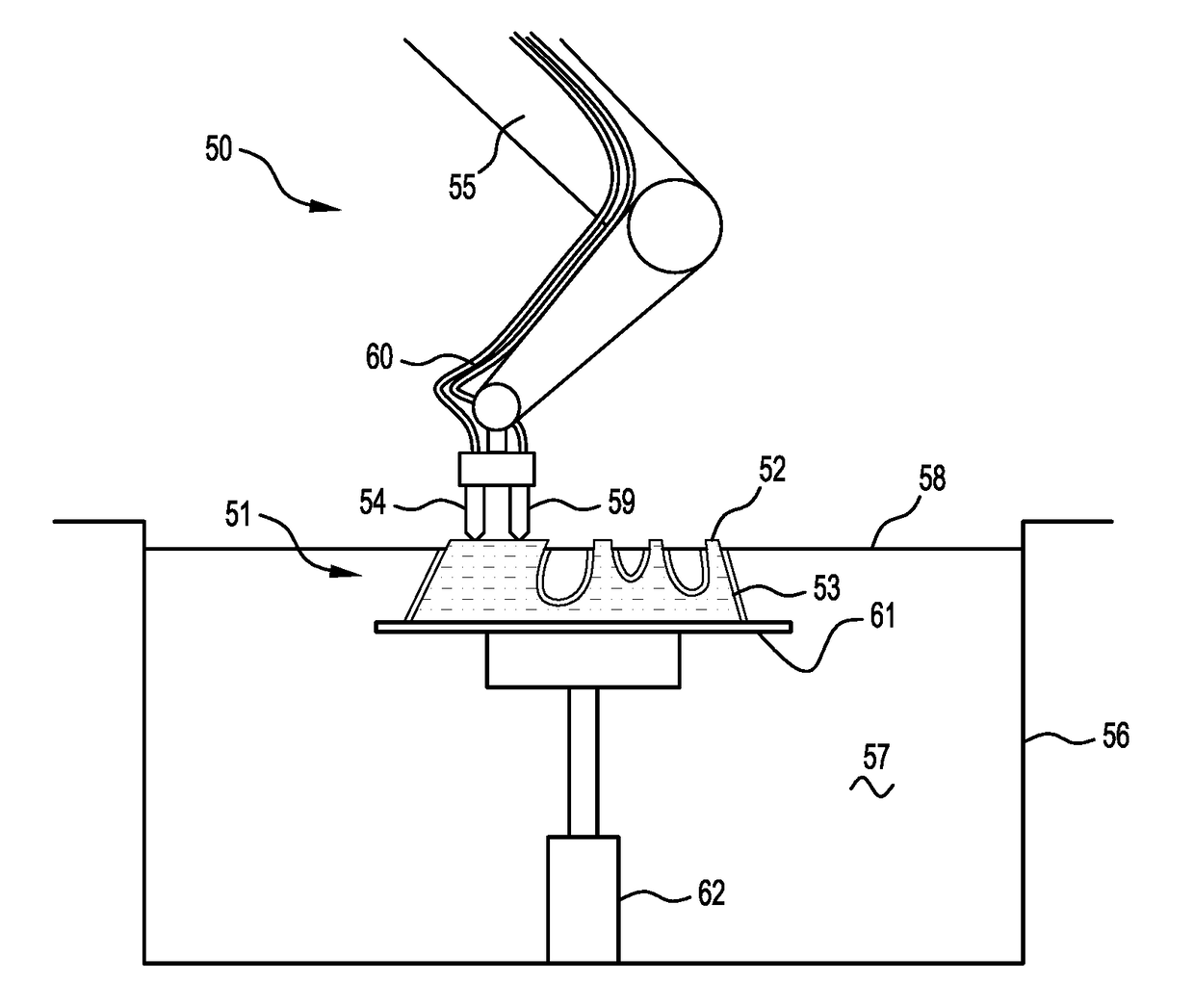
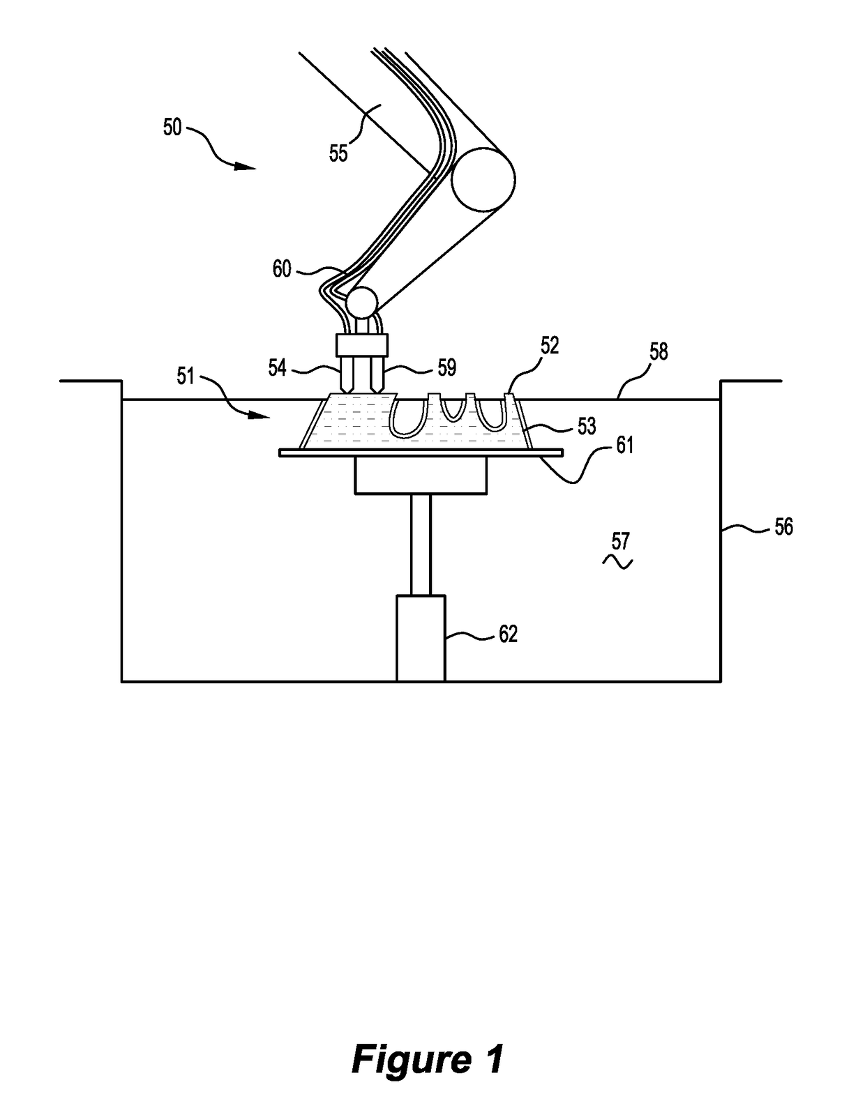
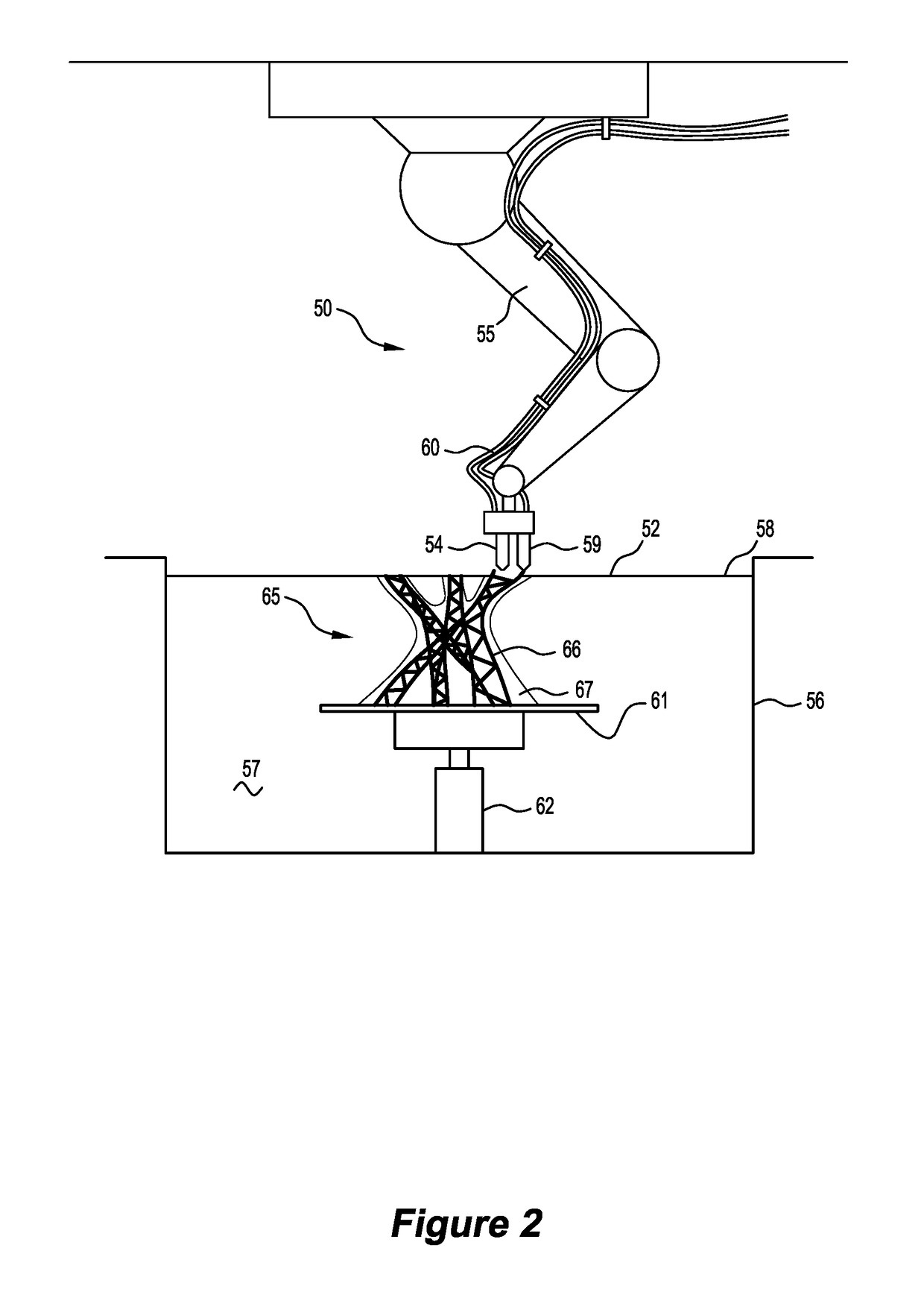
[0023]The present disclosure relates to a method and apparatus for fabricating a composite object, involving selectively solidifying substantially liquid curable first material and selectively depositing a second material in specific locations, the first material and second material thereby forming the composite object.

[0024]FIG. 1 shows a computer-controlled apparatus 50 fabricating a composite object 51 comprising a core 52 formed integrally with a shell 53. The apparatus 50 has an activation head 54 connected to a robotic arm 55 arranged above a reservoir 56 at least partially filled with a substantially liquid, curable first material 57 defining a top surface 58. The activation head 54 is in communication with an energy source (not shown), such as an ultraviolet laser or lamp, which is suitable for curing the curable first material 57. When operated, the activation head 54 exposes and may also focus the energy source on the reservoir 56. A deposition head 59 is arranged adjacent...


PUM

PropertyMeasurementUnit
Structureaaaaaaaaaa

Abstract

A method for fabricating a composite object with a computer-controlled apparatus, and the apparatus therefor. The comprises a reservoir containing liquid, curable first material, means to selectively solidify the first material and means to selectively deposit a second material. The method involves the steps of selectively depositing portions of the second material, and selectively solidifying portions of the first material, such that the solidified portions of the first material and the deposited portions of the second material form the composite object.

Description

TECHNICAL FIELD[0001]The present invention relates generally to fabricating a composite object comprising two or more materials and in particular, relates to fabricating a composite object from a substantially liquid, curable material with a computer-controlled apparatus.BACKGROUND TO THE INVENTION[0002]A composite object is typically formed from two or more materials to obtain an advantage from the combined properties of those materials. For example, it is common to fabricate an object such as a bicycle frame from carbon fibre, which is a composite material, as a composite bicycle frame has a beneficial weight to stiffness ratio.[0003]Additive manufacturing, commonly known as 3D printing, is a manufacturing technique used to fabricate objects. An additive manufacturing process typically involves preparing a digital 3D model of the object with computer software, deriving computer instructions from the 3D model which define a series of parallel, planar cross-sections of the object ge...

Claims


Application Information

Patent Timeline
IPC IPC(8): B29C67/00B33Y30/00B33Y50/02B33Y10/00
CPCB29C67/0081B29C67/0088B29C67/0092B29K2105/12B33Y30/00B33Y50/02B29K2105/0058B33Y10/00B29C70/68B29C64/118B29C64/124B29C64/129B29C64/135B29C64/165B29C64/209B29C64/227B29C64/268B29C64/393B29C64/40B29C64/20B29C31/042B29C31/044B29C31/045B29C70/382B29C70/384B29C70/541B29C70/681B29C64/245B29C64/264B29C64/273B29C64/277B29C64/282B29C64/286B29C64/291
Inventor GARDINER, JAMES BRUCE
Owner LAING OROURKE AUSTRALIA PTY LTD
Why Eureka
Try Eureka