Crosswind performance aircraft engine spinner

Active Publication Date: 2017-04-20
GENERAL ELECTRIC CO
View PDF4 Cites 4 Cited by
  • Summary
  • Abstract
  • Description
  • Claims
  • Application Information

AI Technical Summary

Benefits of technology

[0009]The assembly may further include a spinner axial cross-section having a longer spinner axial distance as compared to a baseline axial distance of a baseline cross-section, the spinner aspect ratio greater than a baseline aspect ratio of the baseline cross-section, the spinner axial cross-section shaped and sized to improve crosswind and/or high angle

Problems solved by technology

Jet engine operations in crosswinds and at high angles of attack can be significantly restricted by fan blade aeromechanics a

Method used


Image

  • Crosswind performance aircraft engine spinner
  • Crosswind performance aircraft engine spinner
  • Crosswind performance aircraft engine spinner

Examples


Example

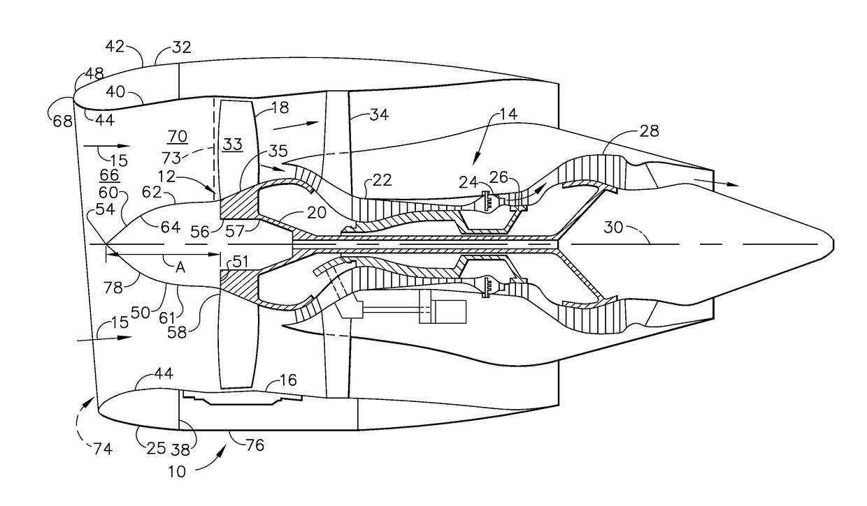
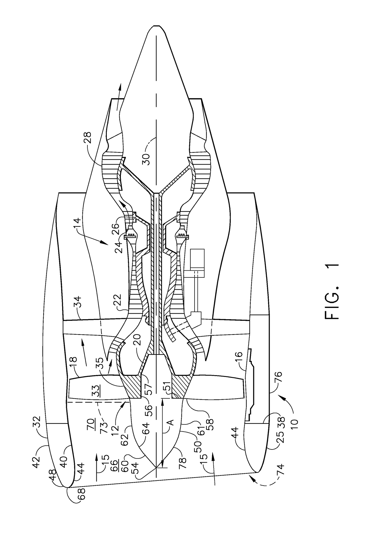
[0014]Illustrated in FIG. 1 is an exemplary embodiment of an aircraft gas turbine engine 10 including a fan assembly 12 and a core engine 14 rotatable about a longitudinally extending engine axial centerline axis 30. The fan assembly 12 includes a fan casing 16 surrounding an array of fan blades 18 extending radially outwardly from a rotor 20. Fan blade airfoils 33 extend radially outwardly from the fan blade platform 35 of each of the fan blades 18. Alternatively, the blades and airfoils may be mounted on a BLISK of the rotor. The core engine 14 includes a high-pressure compressor 22, a combustor 24, a high pressure turbine 26. A low pressure turbine 28 drives the fan blades 18.

[0015]The engine 10 is mounted within a nacelle 32 connected to the fan casing 16 of the engine 10. The fan casing 16 is surrounded by and disposed within the nacelle 32 and circumscribed about the fan blades 18 and supports the fan assembly 12 through a plurality of circumferentially spaced struts 34. The n...


PUM


Abstract

Aircraft gas turbine engine spinner includes conical forward spinner section extending aftwardly from spinner tip to a curved aft spinner section circumscribed about centerline axis, a spinner aspect ratio greater than about 1.8, and wherein spinner aspect ratio is an axial distance between spinner tip and spinner end divided by radial distance from axis to spinner end. Aspect ratio may be in a range of about 2.0-2.2 or about 2.2-2.8. Aft spinner section may be substantially tangential to platform leading edges of platforms of fan blades. Aft spinner section may have cambered or an elliptical axially curved cross-section. Spinner axial cross-section may have longer spinner axial distance compared to baseline axial distance of baseline cross-section and spinner aspect ratio greater than baseline aspect ratio of baseline cross-section.

Description

TECHNICAL FIELD[0001]The present invention relates to aircraft engine spinners and, more particularly, to shape and size of the spinners.BACKGROUND INFORMATION[0002]A gas turbine engine typically includes a fan section, a compressor section, a combustor section and a turbine section. Air entering the compressor section is compressed and delivered into the combustor section where it is mixed with fuel and ignited to generate a high-speed exhaust gas flow. The high-speed exhaust gas flow expands through the turbine section to drive the compressor and a fan in the fan section. The compressor section typically includes low and high pressure compressors, and the turbine section includes low and high pressure turbines.[0003]The fan section includes an inlet which in part may be formed by a nacelle surrounding the fan section and leads to a fan in the fan section. Jet engine operations in crosswinds and at high angles of attack can be significantly restricted by fan blade aeromechanics and...

Claims


Application Information

Patent Timeline
IPC IPC(8): B64D33/02F01D25/24F01D5/02
CPCB64D33/02F01D5/02B64D2033/0286F05D2220/323F05D2240/20F01D25/24F04D29/326B64C11/14F02C7/04F05D2250/232F05D2250/51Y02T50/60
Inventor CLARK, ADAM WAYNECEDAR, RICHARD DAVIDRIDDLE, DAVID BAKER
Owner GENERAL ELECTRIC CO
Why Eureka
Try Eureka