
Wiring terminal and motor comprising the same

a technology of wiring terminal and motor, which is applied in the direction of multi-conductor cable end pieces, windings, and magnetic circuit shapes/forms/construction, etc., can solve the problems of insecure connection, large amount of labor and time, and difficulty in connecting enameled wires and lead wires, so as to save a large amount of labor and time, and effectively prevent enameled wires from detaching from the winding post

Active Publication Date: 2017-04-20
ZHONGSHAN BROAD OCEAN
View PDF0 Cites 3 Cited by
  • Summary
  • Abstract
  • Description
  • Claims
  • Application Information

AI Technical Summary

Benefits of technology

The invention provides a wiring terminal that can reliably and efficiently connect lead wires and enameled wires. The connection subassembly and winding post are placed on the mounting subassembly, and the connection subassembly has a notch to clamp and squeeze wire stock. The winding post has a fixing member to securely fix the wire stock. The design also prevents the enameled wire from detaching from the winding post. The mounting sheet of the invention has a convex and concave surface to securely fix it in the slot of the end insulator. Overall, this design saves time and labor and ensures a reliable connection.

Problems solved by technology

However, it is difficult to connect the enameled wire and the lead wire, and the connection is insecure, time and labor consuming.

Method used


Image

  • Wiring terminal and motor comprising the same
  • Wiring terminal and motor comprising the same
  • Wiring terminal and motor comprising the same

Examples


example 1

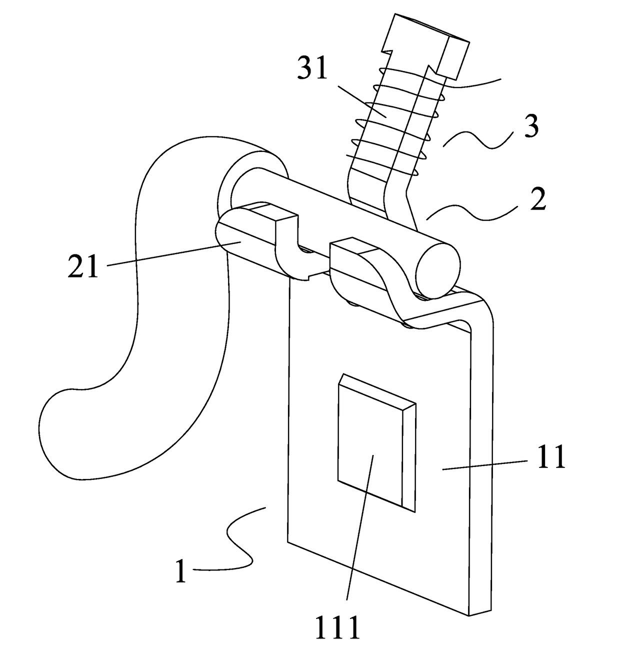
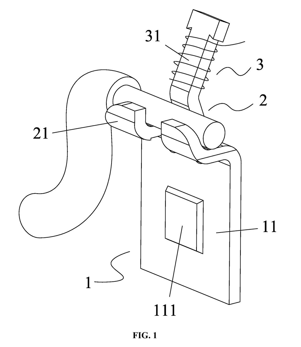
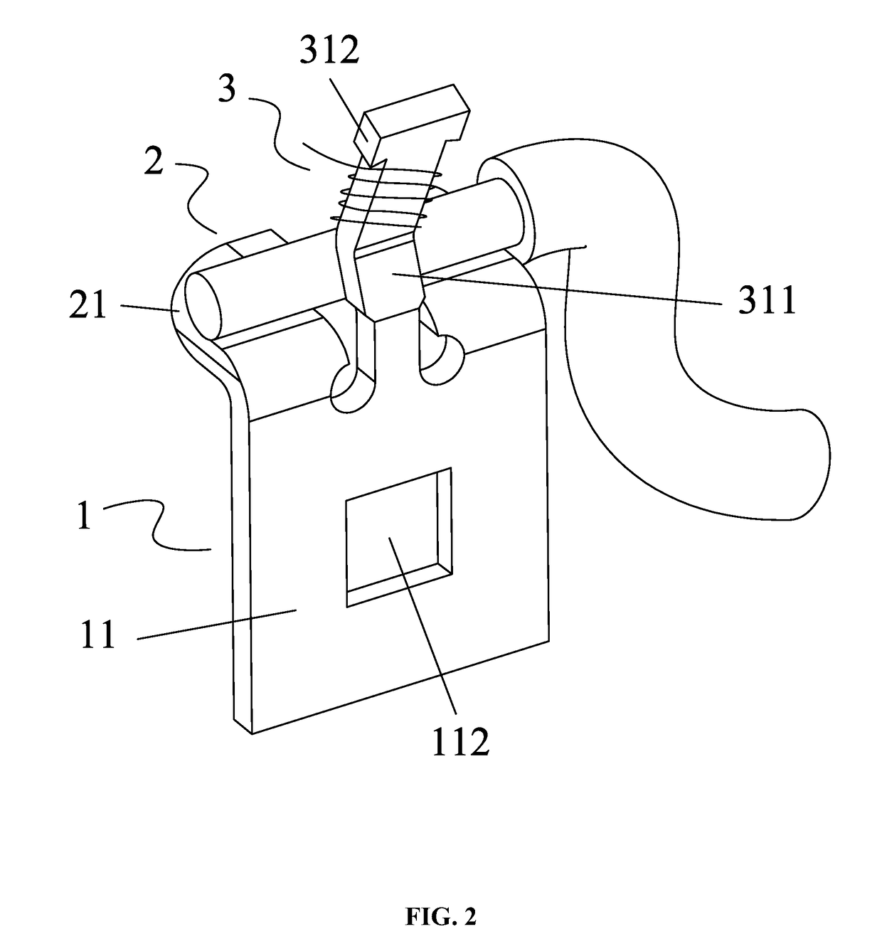
[0031]As shown in FIGS. 1-3, a wiring terminal comprises a mounting subassembly 1, a connection subassembly 2, and a winding subassembly 3. The connection subassembly and the winding subassembly are disposed on the top surface of the mounting subassembly 1. The connection subassembly is adapted to clamp and squeeze a wire stock. An enameled wire is wound on the winding subassembly. As shown in FIGS. 1-2, the wire stock is squeezed by a notch 210, and the enameled wire is wound on a winding post 31. The connection subassembly 2 comprises at least one connecting sheet 21. The at least one connecting sheet protrudes outwards from the top surface of the mounting subassembly 1. The at least one connecting sheet 21 is bent upwards to form the notch 210. The notch is adapted to clamp and squeeze the wire stock. The winding subassembly 3 comprises the winding post 31. The winding post protrudes from the top surface of the mounting subassembly 1. The at least one connecting sheet 21 is two i...

example 2

[0032]As shown in FIGS. 1-7, an external rotor motor comprises a rotary shaft 4, a plastic-packaged stator 5, and an external rotor 6. The plastic-packaged stator 5 is disposed in a chamber 60 of the external rotor 6. The plastic-packaged stator 5 comprises a sleeve base 51, a stator core 52, an end insulator 53, coil windings 54, and a plastic-packaged body 55. The end insulator 53 is disposed on one end surface of the stator core 52. The coil windings 54 are wound on the end insulator 53. The sleeve base 51 is disposed in a shaft hole of the stator core 52. Bearing housings 510 are disposed on two ends of the sleeve base 51. A bearing 7 is disposed in each bearing housing 510. The rotary shaft 4 is disposed in the sleeve base 51, and two ends of the rotary shaft are supported by the bearing 7. The sleeve base 51, the stator core 52, the end insulator 53, and the coil windings 54 are disposed in the plastic-packaged body 55. One end of the rotary shaft 4 protrudes out from the slee...


PUM


Abstract

A wiring terminal and a motor including the wiring terminal are provided. The wiring terminal includes: a mounting subassembly adapted to embed in a slot of an end insulator of a motor, a connection subassembly configured to support a wire stock having a lead wire, and a winding subassembly configure to receive an enameled wire wound on the winding subassembly. The connection subassembly and the winding subassembly are disposed on the top surface of the mounting subassembly. The lead wire of the wire stock is electrically connected to the enameled wire wound on the winding subassembly.

Description

CROSS-REFERENCE TO RELATED APPLICATIONS[0001]This application is a continuation-in-part of International Patent Application No. PCT / CN2015 / 090339 with an international filing date of Sep. 23, 2015, designating the United States, now pending, and further claims foreign priority benefits to Chinese Patent Application No. 201520435528.1 filed Jun. 23, 2015. The contents of all of the aforementioned applications, including any intervening amendments thereto, are incorporated herein by reference. Inquiries from the public to applicants or assignees concerning this document or the related applications should be directed to: Matthias Scholl P.C., Attn.: Dr. Matthias Scholl Esq., 245 First Street, 18th Floor, and Cambridge, Mass. 02142.BACKGROUND OF THE INVENTION[0002]Field of the Invention[0003]The invention relates to a wiring terminal and a motor comprising the same.[0004]Description of the Related Art[0005]The wiring processes for conventional motors include: electrically connecting the...

Claims


Application Information

Patent Timeline
Patent Type & Authority Applications(United States)
IPC IPC(8): H02K3/52H02K3/18H02K5/02H02K1/14
CPCH02K3/521H02K5/02H02K3/18H02K1/145H01R11/11H01R4/14H02K3/522
Inventor FU, GUIWENWANG, XIONGCHENGZHU, JINCHENG
Owner ZHONGSHAN BROAD OCEAN
Learn More