Heat dissipating system

Inactive Publication Date: 2017-04-20
COOLER MASTER CO LTD
View PDF15 Cites 17 Cited by
  • Summary
  • Abstract
  • Description
  • Claims
  • Application Information

AI Technical Summary

Benefits of technology

[0009]The heat dissipating system in the present invention can be integrated on a cooling tank so that the space necessary for the heat dissipating system is smaller than before and can be flexibly arranged, and the

Problems solved by technology

However, the flexibility of space arrangement is difficult since a certain amount of space is re

Method used


Image

  • Heat dissipating system
  • Heat dissipating system
  • Heat dissipating system

Examples


Example

[0015]The present invention will now be described more specifically with reference to the following embodiments. It is to be noted that the following descriptions of preferred embodiments of this invention are presented herein for purpose of illustration and description only. It is not intended to be exhaustive or to be limited to the precise form disclosed.

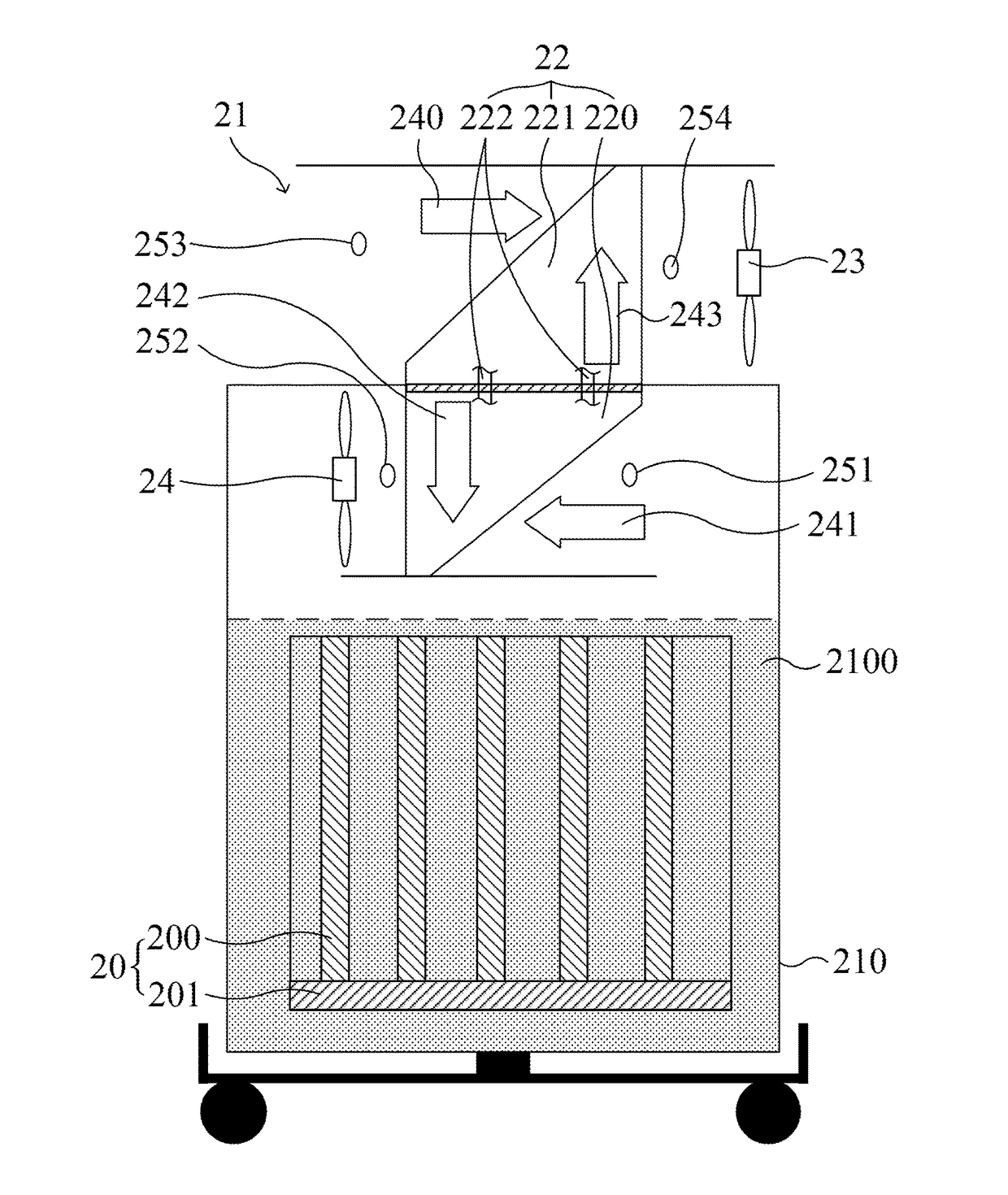
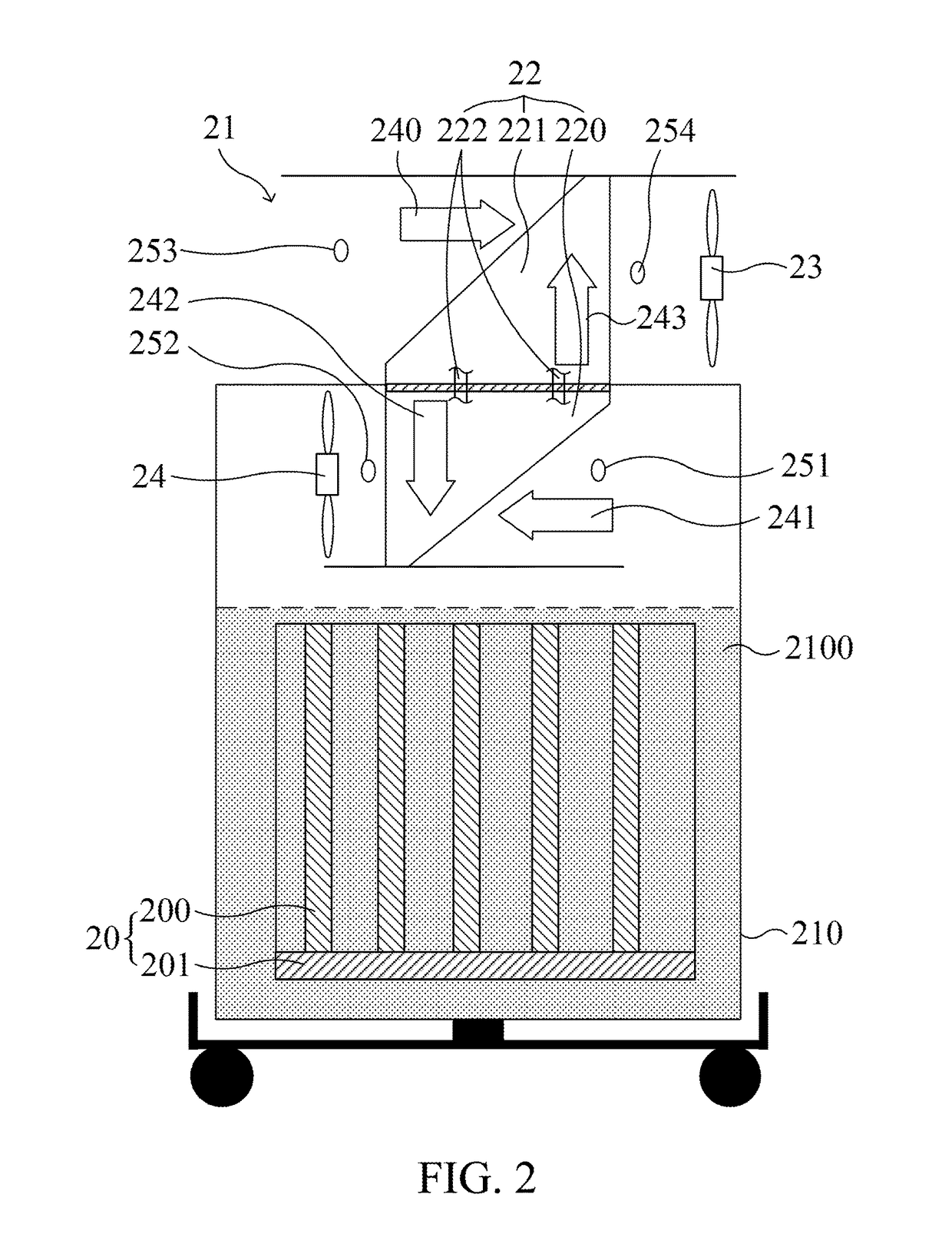
[0016]Please refer to FIG. 2, which is a functional block diagram of a heat dissipating system according to one embodiment of the present invention. The heat dissipating system 21 could be widely applied on any kinds of heat element, especially for those circuit modules such as the data center 20 comprising a server with a plurality of mainboards 200 and a backboard 201 shown in this figure. The heat dissipating system 21 in this embodiment primarily comprises a cooling tank 210. The cooling tank 210 is used for storing a cooling liquid 2100 and disposing the data center 20. In one embodiment, the cooling liquid 2100 could be a d...


PUM


Abstract

A heat dissipating system provided herein comprises a cooling tank for storing a cooling liquid and a heat element, wherein the cooling liquid is phase-changed into a working gas due to thermal energy generated by the heat element; an evaporator installed in the cooling tank for absorbing thermal energy of the working gas; a condenser uncovered by the cooling tank; at least one communicating member communicated with the evaporator and the condenser and filled with a coolant, wherein the coolant is heated in the evaporator and flows to the condenser through the communicating member in a gaseous state, and, after being cooled in the condenser, recovers into a liquid state and then returns to the evaporator through the communicating member; and a first gas driving module for driving air to flow around the condenser.

Description

FIELD OF THE INVENTION[0001]The present invention relates to a heat dissipating system. Specifically, the present invention relates to a heat dissipating system applied on a heat element.BACKGROUND OF THE INVENTION[0002]Please refer to FIG. 1, which is a functional block diagram of a conventional heat dissipating system applied on a data center, wherein a plurality of mainboards 11 of a server are disposed in a cooling tank having a dielectric cooling liquid 100 with a boiling point between 40 to 60° C., such as the Novec Engineered Fluids produced by 3M. Accordingly, a temperature at which the server normally operates would result in boiling of the dielectric cooling liquid 100 characterized in electrical insulation in the cooling tank 10. The boiled dielectric cooling liquid 100 is vaporized, collected through the upper cover 101 and the vapor trapper 102, returned into the liquid state from the gaseous state by the condenser 12, and finally flows back to the semi-opened cooling t...

Claims


Application Information

Patent Timeline
IPC IPC(8): H05K7/20F28D15/06F28D15/02
CPCH05K7/208F28D15/0266F28D15/06F28D15/025F28D15/0275H05K7/20818F28D15/02H05K7/203H05K7/20236
Inventor WANG, YAO-CHUN
Owner COOLER MASTER CO LTD
Why Eureka
Try Eureka