Exercise Machine with Multiple Contact Surfaces

a technology of exercise machines and contact surfaces, applied in the direction of gymnastic exercise, sport apparatus, cardiovascular exercise devices, etc., can solve the problems of not being able to provide a large surface area, not being able to support the weight of an exerciser, and being substantially small in cross sectional dimensions

Active Publication Date: 2017-04-27
LAGREE TECH INC
View PDF0 Cites 68 Cited by
  • Summary
  • Abstract
  • Description
  • Claims
  • Application Information

AI Technical Summary

Benefits of technology

[0011]An example embodiment of the present invention is directed to an exercise machine with multiple contact surfaces. The exercise machine with multiple contact surfaces includes a plurality of resting platforms fixed at various dimensions vertically positioned above the horizontal plane of the slidable carriage of a Pilates apparatus. The plurality of platforms thereby provide for surfaces providing for grasping by the hands, supporting the exercisers' arms, resistant to pushing force applied by exercisers' feet or supportive of the entire weight of an exerciser upon the apparatus, and which further provides for ergonomically correct hand-gripping positions used by all different sized exercisers when performing various exercises upon the apparatus.
[0012]The width of the handle platforms are preferably of a dimension that provides for comfortable gripping by the exerciser's hands, while at the same time provides for comfortably cushioning exercisers who apply substantial downward or lateral force against the platform by distributing such forces to an adequately large platform surface area upon which a hand, arm, foot or entire body weight is placed.
[0018]Yet another exemplary embodiment of the present invention is a handle of an improved exercise apparatus, the substantially horizontal top surface of the platform usable as a handle for easy gripping by a hand with the palm facing vertically downward, and a substantially vertically aligned portion of the platform of sufficient surface area as to provide for supporting substantially the entire foot of an exerciser pressing horizontally upon the handle with their foot.

Problems solved by technology

One major problem of the crossbar on Pilates machines is that the crossbar is not designed to support the weight of an exerciser since it is used for push and pull type exercises.
Another problem with the crossbar is that the cross sectional dimension is substantially small, for instance, a one-inch diameter bar, and does not provide for a large surface area against which an exerciser can comfortably push against with bare feet.
The small bar will cause pain, and inherently inhibits an exerciser from maximizing the exercise resistance for the workout because of the foot pain caused by the increased resistance force.
Another problem is that the cross bar is intended to be used when an exerciser is substantially positioned upon the slidable carriage with their shoulders substantially parallel to the cross bar.
In such instances, the foot, having an extremely small surface against which to push, may slip off of the cross bar causing injury, or at the least, causing the exerciser to stop exercising.
In most all cases, the alignment of the length of the foot against the longitudinal axis of the narrow cross bar will cause the exerciser foot pain throughout the foot-pressing exercise.
Yet another problem with the cross bar as just described is that the height of the cross bar is typically positioned at a fixed dimension above the primary horizontal plane of the slidable platform.
Since the height of people who exercise vary significantly for instance, the shorter exercisers perhaps being under five feet in height, and the taller exercisers being up to seven feet in height, the substantially fixed position of the cross bar fails to provide ergonomically correct positioning of all exercisers.

Method used


Image

  • Exercise Machine with Multiple Contact Surfaces
  • Exercise Machine with Multiple Contact Surfaces
  • Exercise Machine with Multiple Contact Surfaces

Examples


Embodiment Construction

[0046]Various aspects of specific embodiments are disclosed in the following description and related drawings. Alternate embodiments may be devised without departing from the spirit or the scope of the present disclosure. Additionally, well-known elements of exemplary embodiments will not be described in detail or will be omitted so as not to obscure relevant details. Further, to facilitate an understanding of the description, a discussion of several terms used herein follows. All distances and lengths using specific measurements are approximations only and are not limited to the specific measurement indicated and should be interpreted to include any measurement reasonably adjacent or near the stated measurement.

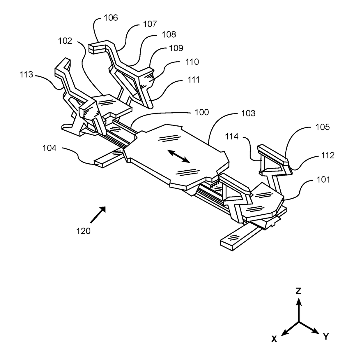
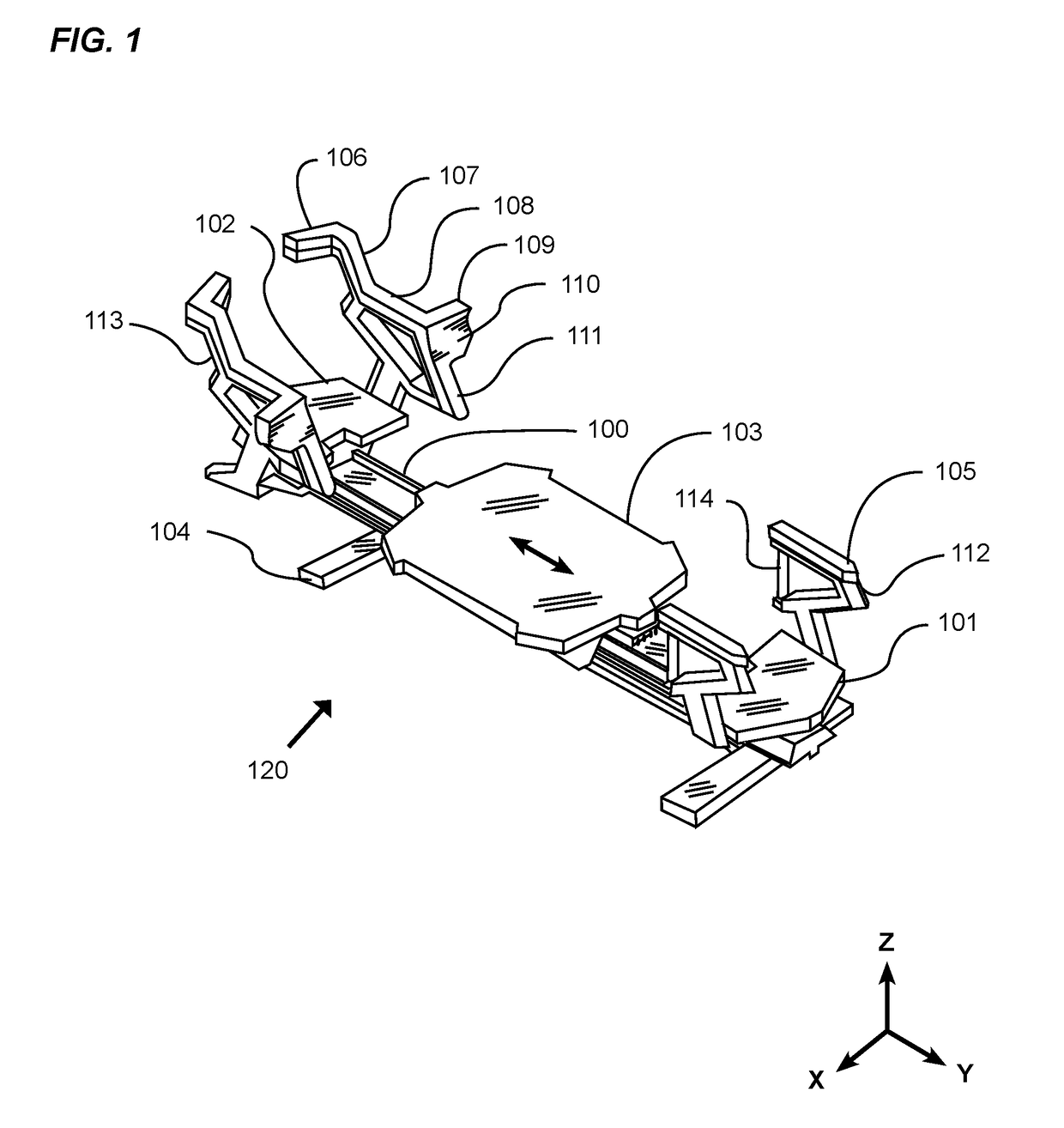
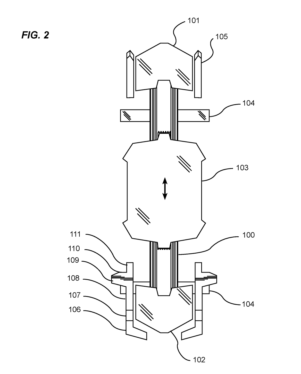
[0047]“Platform” as used herein may also mean supporting surface upon which an exerciser can place all or part of their body during the performance of an exercise. The platform may have a supporting surface that is aligned substantially with the horizontal surface of the pri...


PUM


Abstract

An exercise machine with multiple contact surfaces for providing secondary exercise support platforms positioned at various planes relative to the horizontal plane of the primary exercising platforms, the secondary platforms further serving as handles used during the performance of exercises. The exercise machine with multiple contact surfaces generally includes a frame, a carriage movably attached to the rail, and a first support structure and a second support structure attached to the frame near the first end. The support structures each include one or more platforms having an upper surface that is positioned above the base plane of the carriage.

Description

CROSS REFERENCE TO RELATED APPLICATIONS[0001]I hereby claim benefit under Title 35, United States Code, Section 119(e) of U.S. provisional patent application Ser. No. 62 / 244,275 filed Oct. 21, 2015. The 62 / 244,275 application is currently pending. The 62 / 244,275 application is hereby incorporated by reference into this application.STATEMENT REGARDING FEDERALLY SPONSORED RESEARCH OR DEVELOPMENT[0002]Not applicable to this application.BACKGROUNDField[0003]Example embodiments in general relate to an exercise machine with multiple contact surfaces for providing secondary exercise support platforms positioned at various planes relative to the horizontal plane of the primary exercising platforms, the secondary platforms further serving as handles used during the performance of exercises.Related Art[0004]Any discussion of the related art throughout the specification should in no way be considered as an admission that such related art is widely known or forms part of common general knowledg...

Claims


Application Information

Patent Timeline
Patent Type & Authority Applications(United States)
IPC IPC(8): A63B21/00A63B21/068A63B22/00A63B21/055
CPCA63B21/4035A63B21/0552A63B22/0023A63B21/4045A63B21/068A63B21/023A63B23/0211A63B23/0216A63B23/0233A63B23/03525A63B23/0405A63B23/1209A63B2208/0219A63B2208/0247A63B2208/0252A63B2208/0295A63B21/4034A63B22/0087
Inventor LAGREE, SEBASTIEN ANTHONY LOUIS
Owner LAGREE TECH INC
Why Eureka
Try Eureka