Camshaft adjuster including a discharge valve

a technology of camshaft adjuster and discharge valve, which is applied in the direction of mechanical equipment, machines/engines, engine components, etc., can solve the problems of reducing the service life of the camshaft, affecting the service life of the cam, etc., to achieve the effect of reducing the pressure on the locking pin, long flow paths, and high hydraulic resistan

Active Publication Date: 2017-04-27
SCHAEFFLER TECH AG & CO KG
View PDF0 Cites 0 Cited by
  • Summary
  • Abstract
  • Description
  • Claims
  • Application Information

AI Technical Summary

Benefits of technology

[0008]According to the prior art, a complicated switch valve is generally necessary for suitable emptying of the hydraulic channel and relieving pressure on the locking pin. Complicated additional devices, for example a separate control channel for the locking pins, may be necessary due to the fixed cross section of the flow paths of the hydraulic medium. Relatively long flow paths and high hydraulic resistances result in relatively long pressure relief times until the camshaft adjuster is locked.
[0009]An object of the present invention is to provide a camshaft adjuster which does not have the above-mentioned disadvantages, or has them only to a lesser extent. In particular, the aim is to be able to achieve faster locking of the camshaft adjuster, in particular after the engine is switched off.
[0010]The present invention provides that at least one additional discharge channel which includes a discharge valve and which is fluidically connected to the hydraulic channel is formed in the rotor, it being innovative that the discharge valve closes the discharge channel when the locking pin is acted on by pressure, and opens the discharge channel when the hydraulic pressure acting on the locking pin drops. Due to the present invention, when there is a pressure drop, for example due to switching off the engine, at least one additional flow path is opened through which hydraulic medium may flow to the tank. The present invention yields the advantage that the pressure drop at the locking pin takes place very quickly, for example within a period of 1 second, preferably within approximately 0.6 to 0.3 seconds, particularly preferably within approximately 0.4 seconds, so that, due to the pretension acting on it, the locking pin may arrive at the position in which the rotor is locked with the cover, at the desired, required high speed.

Problems solved by technology

Relatively long flow paths and high hydraulic resistances result in relatively long pressure relief times until the camshaft adjuster is locked.

Method used


Image

  • Camshaft adjuster including a discharge valve
  • Camshaft adjuster including a discharge valve
  • Camshaft adjuster including a discharge valve

Examples


Embodiment Construction

[0029]The figures are merely schematic, and are used only for an understanding of the present invention. Identical elements are provided with the same reference numerals. Details of the various exemplary embodiments may also be combined and / or exchanged with one another.

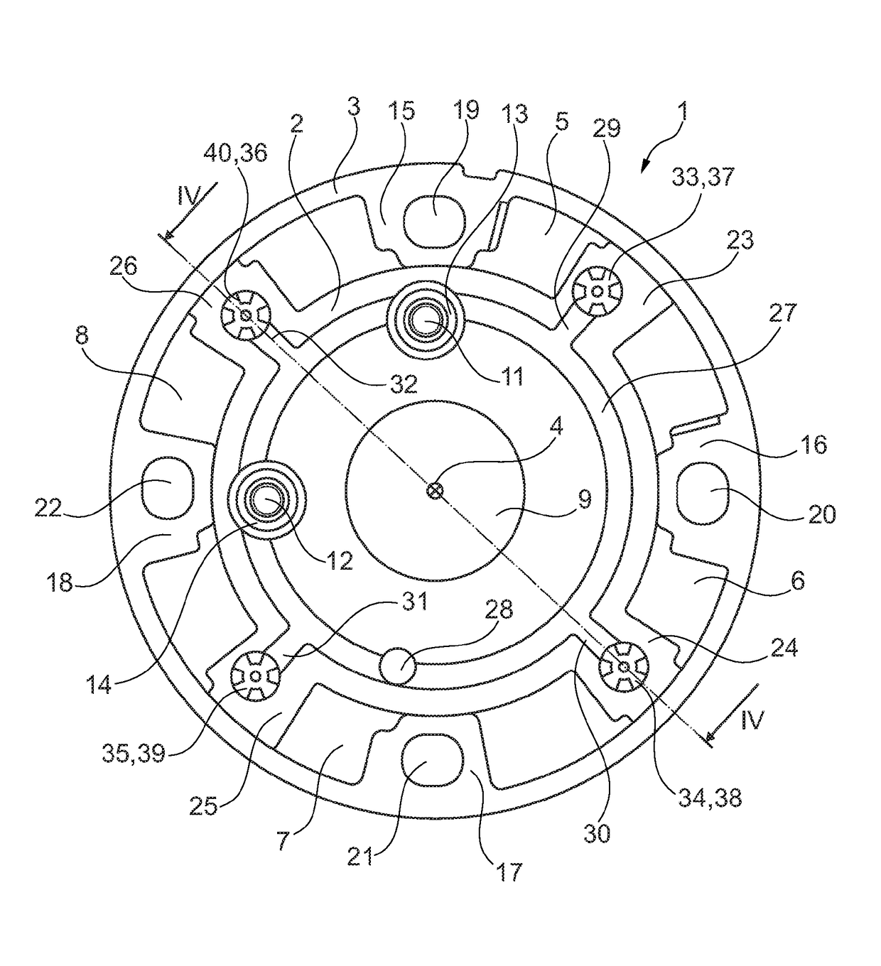
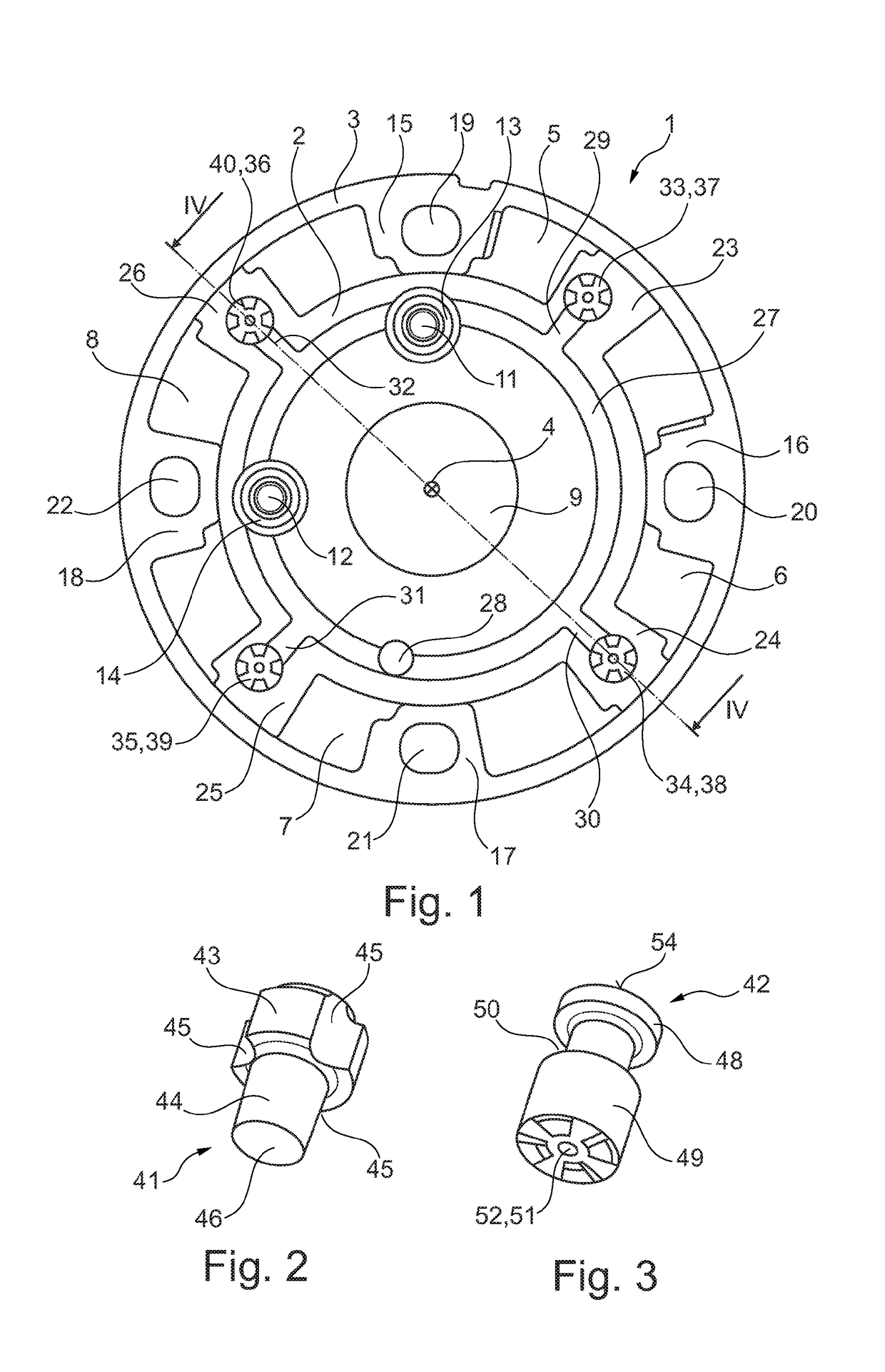
[0030]FIG. 1 shows a camshaft adjuster 1 according to the present invention in a top view, without a cover. Camshaft adjuster 1 is used for adjusting the rotation angle of a camshaft, not shown, with respect to the crankshaft of an internal combustion engine. The gas exchange valves of the internal combustion engine are actuated with the aid of the camshaft. The optimum valve timing changes with the engine speed. For the intake valves, the timing is retarded with increasing engine speed, and for the exhaust valves it is advanced. For engines having separate camshafts for the intake valves and exhaust valves, there is the option of easily achieving the desired speed-dependent adaptation of the timing by appropriately ...


PUM


Abstract

A hydraulic camshaft adjuster (1), in particular a vane-type hydraulic camshaft adjuster, including a rotor (2) and a stator (3) which are mounted to rotate with respect to each other, a cover (10) fixed on the stator (3), including a locking receiver and at least one locking pin (11, 12) accommodated in the rotor (2), the locking pin being slidable in the axial direction and prestressed in the direction of the locking receiver, and a hydraulic channel (27, 28, 29) to apply pressure of the locking pin (11, 12) against the prestress of same, the hydraulic channel being able to be filled and emptied with a hydraulic medium via a central screw, wherein in the rotor (2) at least one additional discharge channel (37, 38, 39, 40) fluidically connected to the hydraulic channel (27, 28, 29) is formed with a discharge valve (33, 34, 35, 36), wherein preferably the discharge valve (33, 34, 35, 36) closes the discharge channel (37, 38, 39, 40) when the locking pin (11, 12) is pressurized and opens the discharge channel when the hydraulic pressure acting on the locking pin (11, 12) falls.

Description

[0001]The present invention relates to a hydraulic camshaft adjuster, in particular a hydraulic camshaft adjuster of the vane cell type, which includes a rotor and a stator which are supported in such a way that they are rotatable relative to one another, a cover which is fixed to the stator and which includes a locking receptacle, a locking pin which is accommodated in the rotor in such a way that the locking pin is displaceable in the axial direction, and is pretensioned in the direction of the locking receptacle, and a hydraulic channel for acting with pressure on the locking pin against its pretension, it being possible to fill the hydraulic channel with a hydraulic medium and empty same via a central screw.BACKGROUND[0002]Camshaft adjusters are used for a targeted adjustment of the phase position between a camshaft and a crankshaft in an internal combustion engine. They allow an optimized setting of valve timing via the engine load and the engine speed. In this way, fuel consum...

Claims


Application Information

Patent Timeline
Patent Type & Authority Applications(United States)
IPC IPC(8): F01L1/344
CPCF01L1/3442F01L2001/34453F01L2001/34426F01L2001/34433F01L2001/34466F01L2001/34469F01L1/46
Inventor THIELEN, JOCHENBOESE, OLAFZSCHIESCHANG, TORSTEN
Owner SCHAEFFLER TECH AG & CO KG
Why Eureka
Try Eureka