Shaft coupling mechanism for electric power steering apparatus

a technology of electric power steering and coupling mechanism, which is applied in the direction of couplings, electric steering, yielding couplings, etc., can solve the problems of unfavorable steering feel for drivers, and achieve the effect of suppressing abnormal noise and unpleasant steering feel

Inactive Publication Date: 2017-04-27
OILES CORP
View PDF1 Cites 8 Cited by
  • Summary
  • Abstract
  • Description
  • Claims
  • Application Information

AI Technical Summary

Benefits of technology

[0024]According to the present invention, it is possible to provide a shaft coupling mechanism for an electric power steering apparatus which makes it possible to avoid the radial collision between the rotating shaft and the rotation transmitting member and suppress the generation of the abnormal noise which imparts an unpleasant steering feel to the driver.

Problems solved by technology

In the case where the steering shaft and the rotating shaft are coupled by means of the shaft coupling mechanism, there is a possibility that an impact at the time of the reversing of the output rotating shaft of the electric motor and the vibration of the brushes of the electric motor are transmitted to the steering wheel through the shaft coupling mechanism and the steering shaft, thereby causing an unpleasant steering feel to the driver.

Method used


Image

  • Shaft coupling mechanism for electric power steering apparatus
  • Shaft coupling mechanism for electric power steering apparatus
  • Shaft coupling mechanism for electric power steering apparatus

Examples


Embodiment Construction

[0042]Next, a more detailed description will be given of the mode for carrying out the invention on the basis of a preferred embodiment illustrated in the drawings. It should be noted that the present invention is not limited to such an embodiment.

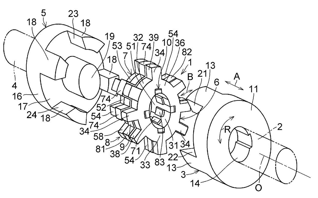
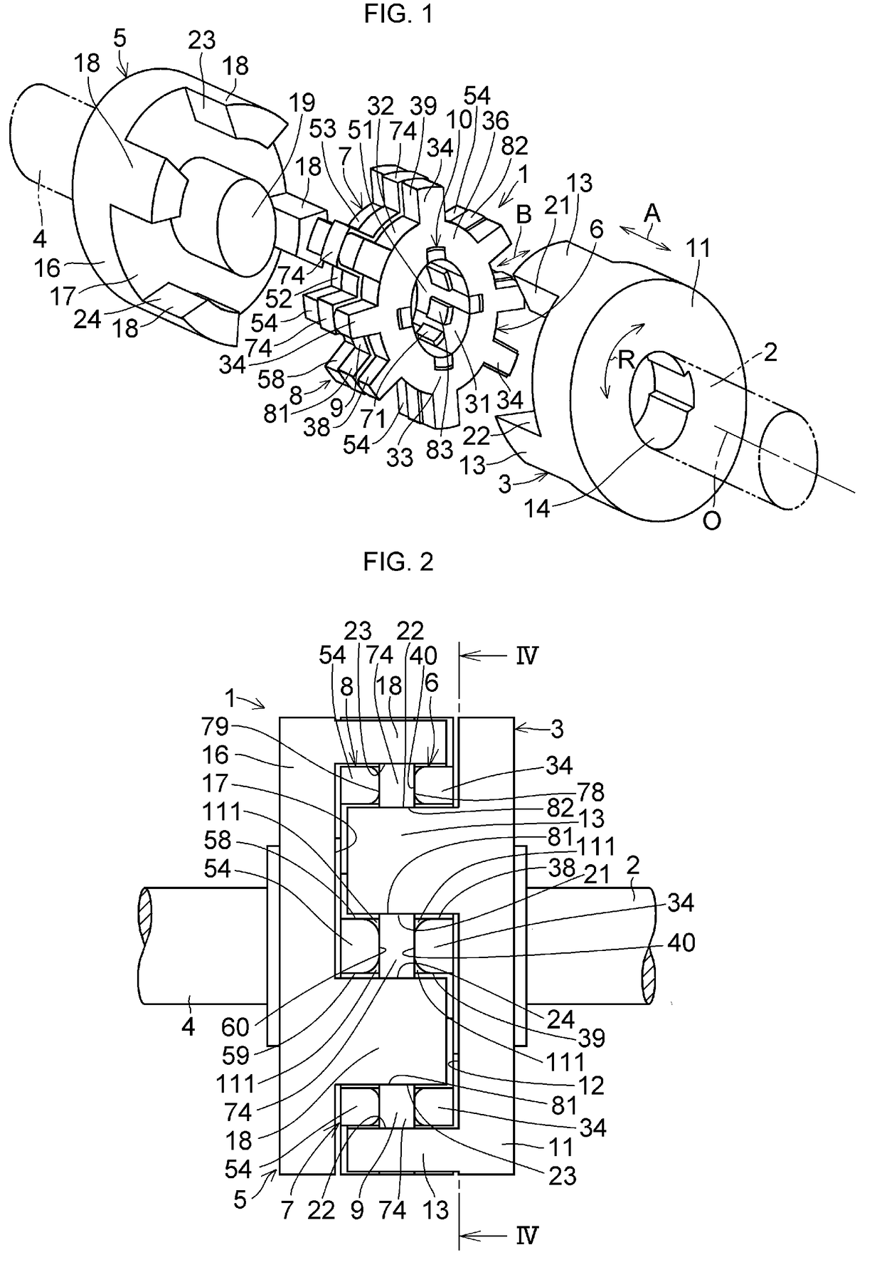
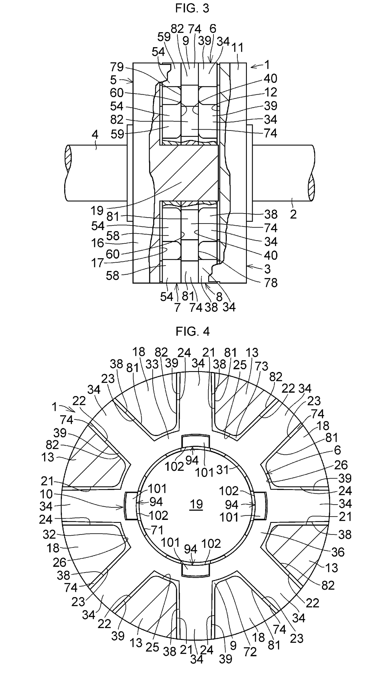
[0043]In FIGS. 1 to 17, a shaft coupling mechanism 1 for an electric power steering apparatus in accordance with this embodiment is comprised of a coupling base body 3 coupled to a rotating shaft 2; a coupling base body 5 coupled to a rotating shaft 4; a rotation transmitting member 8 constituted by a pair of rigid rotation transmitting members 6 and 7 disposed between the rotating shaft 2 and the rotating shaft 4 through both coupling base bodies 3 and 5 and adapted to transmit the rotation of the rotating shaft 2 in an R direction about an axis 0 to the rotating shaft 4; an elastic member 9 interposed between the rotation transmitting members 6 and 7 and coupled to the rotation transmitting members 6 and 7 in such a manner as to be axial...


PUM


Abstract

A shaft coupling mechanism 1 for an electric power steering apparatus includes a coupling base body 3 coupled to a rotating shaft 2; a coupling base body 5 coupled to a rotating shaft 4; a rotation transmitting member 8 constituted by a pair of rigid rotation transmitting members 6 and 7 disposed between the rotating shaft 2 and the rotating shaft 4 through both coupling base bodies 3 and 5 and adapted to transmit the rotation of the rotating shaft 2 in an R direction about an axis O to the rotating shaft 4; an elastic member 9 interposed between the rotation transmitting members 6 and 7 and coupled to the rotation transmitting members 6 and 7 in such a manner as to be axially superposed on the rotation transmitting members 6 and 7; and a coupling means 10 for coupling the pair of rotation transmitting members 6 and 7 to each other.

Description

TECHNICAL FIELD[0001]The present invention relates to a shaft coupling mechanism suitable for coupling a rotating shaft on a rotating source side such as an electric motor in an electric power steering apparatus and a rotating shaft on an operating side such as a steering shaft of an automobile.BACKGROUND ART[0002]An electric power steering apparatus is for facilitating the manual steering of a steering wheel by adding a torque based on the rotation of an output rotating shaft of an electric motor to a torque based on the rotation of the steering wheel which is manually operated. In such an electric power steering apparatus, the steering shaft on the steering wheel side and the rotating shaft on the output rotating shaft side of the electric motor are coupled by means of a shaft coupling mechanism (a coupling).[0003]In the case where the steering shaft and the rotating shaft are coupled by means of the shaft coupling mechanism, there is a possibility that an impact at the time of th...

Claims


Application Information

Patent Timeline
Patent Type & Authority Applications(United States)
IPC IPC(8): F16D3/72F16D3/12
CPCF16D3/72B62D5/04F16D3/12F16D3/68F16D3/74
Inventor YAMAGUCHI, SHUICHINAKAGAWA, NOBORU
Owner OILES CORP
Why Eureka
Try Eureka